2005 PDI: Dyna Models 3-3
THROTTLE CABLES
Twist and release throttle control grip a few times to verify
proper operation of throttle control system. With throttle fric-
tion screw loosened, carburetor throttle must return to idle
position each time throttle control grip is released.
1WARNING1WARNING
Throttle cables must not pull tight when handlebars are
turned fully to left or right fork stops. Be sure wires and
throttle cables are clear of fork stops at steering head so
they will not be pinched when fork is turned against
stops. Steering must be smooth and free with no binding
or interference. Interference with steering could cause
loss of vehicle control which could result in death or
serious injury.
Check throttle cable adjustment. With engine running, turn
handlebars through full range of travel. If engine speed
changes during this maneuver, adjust throttle cables as fol-
lows:
1. See Figure 3-2. Slide rubber boot (if applicable) off each
cable adjuster.
2. Loosen jam nut (5) on each adjuster (4).
3. Turn adjusters in direction which will shorten cable hous-
ings to minimum length.
4. Point front wheel straight ahead. Twist throttle control
grip to fully open position; hold in position.
5. See Figure 3-1. Tu rn adjuster on throttle control cable
until throttle cam stop (4) touches carburetor stop plate
(1).
6. See Figure 3-2. Tighten jam nut (5) on throttle control
cable (2) adjuster (4); release throttle control grip.
7. See Figure 3-1. Turn handlebars fully to right. Turn
adjuster on idle control cable until end of cable housing
(2) just touches spring (3) within carburetor cable guide.
8. See Figure 3-2. With throttle friction screw (1) loosened,
twist and release throttle control grip a few times. Carbu-
retor throttle must return to idle position each time throt-
tle grip is released. If this is not the case, turn adjuster
(4) on idle control cable (3) (shortening cable housing)
until throttle control functions properly.
9. Tighten jam nut (5) on idle control cable (3) adjuster (4).
Recheck operation of throttle control (Step 7).
10. Slide rubber boot (if applicable) over each cable adjuster
(4). Recheck engine slow idle speed; adjust if required.
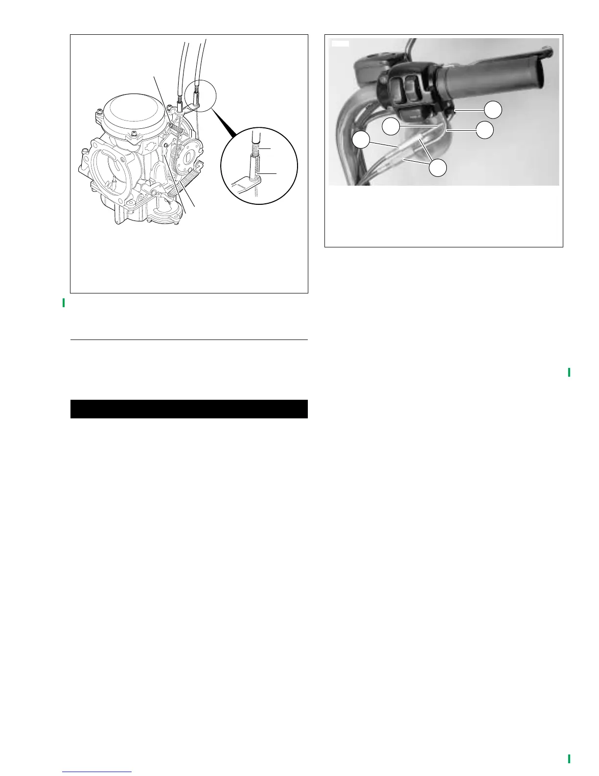
Figure 3-1. Carburetor Adjustments
1. Carburetor stop plate
2. Cable housing
3. Spring
4. Throttle cam stop
5. Idle speed adjusting screw
f1381a2x
4
3
1
5
2
Figure 3-2. Throttle Cable Adjustment
5428
1. Throttle friction screw
2. Throttle control cable
3. Idle control cable
4. Adjuster
5. Jam nut
3
1
2
4
5