5-4 2005 PDI: Sportster Models
MIRRORS
NOTE
XL 883L model: righthand mirror is shipped in protective foam
on left hand grip and must be installed.
1. XL 883L models:
a. See Figure 5-4. Insert mirror (1) stem into hole in
master cylinder assembly (2).
b. Install lock washer (3) and lock nut (4). Tighten to
96-144 in-lbs (10.9-16.3 Nm).
2. Adjust mirrors for proper rear view.
3. Adjust front directional lamps so lenses are aimed
directly forward.
4. Verify that mirror and directional lamp fasteners are prop-
erly tightened.
NOTE
A 4 mm allen wrench will be needed to perform the front
directional adjustments.
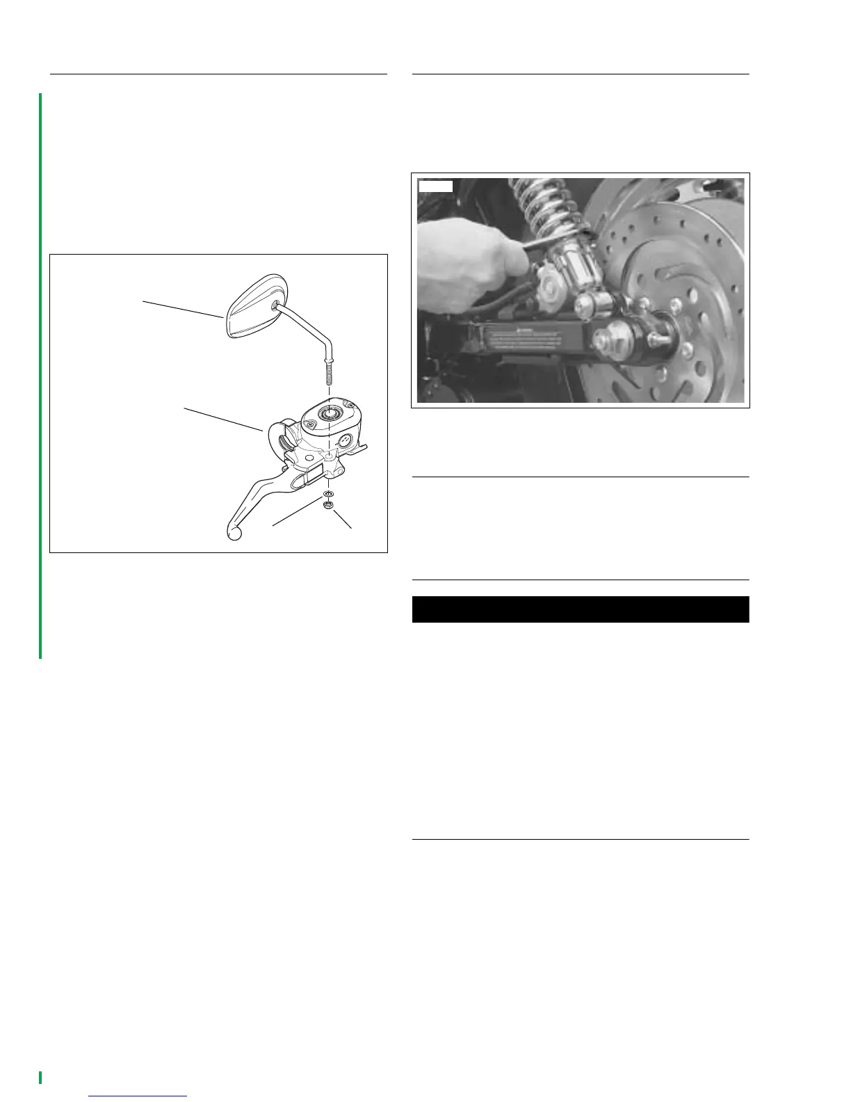
REAR SUSPENSION
See Figure 5-5. Check that spring preload is set the same on
both rear shock absorbers. For a solo rider of average weight,
adjust spring preload to softest setting using SPANNER
TOOL (Part No. HD-94820-75A) for all models.
DIRECTIONAL LAMPS
Adjust rear directional lamps so lenses are aimed directly
rearward. Verify that directional lamp fasteners are properly
tightened.
THROTTLE CONTROL CABLES
1WARNING1WARNING
Throttle cables must not pull tight when handlebars are
turned fully to left or right fork stops. Be sure wires and
throttle cables are clear of fork stops at steering head so
they will not be pinched when fork is turned against
stops. Steering must be smooth and free with no binding
or interference. Interference with steering could cause
loss of vehicle control which could result in death or
serious injury.
Check throttle cable adjustment in accordance with proce-
dure given in Section 1 of Sportster Models Service Manual.
SEATS AND PASSENGER STRAP
Refer to Sportster Models Owner’s Manual for seat and pas-
senger strap removal and installation instructions.
Figure 5-4. Installing Righthand Mirror on XL 883L
pd0225
1. Righthand mirror
2. Front brake master
cylinder assembly
3. Lock washer
4. Lock nut
1
2
4
3
Figure 5-5. Adjusting Spring Preload
10628
 Loading...