2.26HANDLEBARS: FXDWG/FXDF
REMOVAL
To prevent accidental vehicle start-up, which could cause
death or serious injury, disconnect negative (-) battery
cable before proceeding. (00048a)
1. Disconnect negative battery cable.
2. Remove instrument panel. See 8.17 INSTRUMENTS:
FXDWG/FXDC/FXDF.
3. Unplug fuel gauge connector.
4. Remove fuel tank fasteners, vent, fuel supply fitting and
slide fuel tank back. See 4.5 FUEL TANK.
5. Place blanket or protective cover over front of fuel tank to
protect against scratches and other damage.
6. Disconnect all left and right side hand control connectors
from connectors on main harness.
NOTE
Make note of wire colors and locations in connector before
removal. This will ensure proper wire location in connector
during installation.
7. Identify wire leads and remove terminals from hand control
connector housings (left hand control connector [24], right
hand control connector [22]). See A.10 MOLEX CON-
NECTORS.
8. Remove terminals from turn signal multilock connector.
See A.2 AMP MULTILOCK CONNECTORS
9. Remove front master cylinder assembly. See 2.12 FRONT
BRAKE MASTER CYLINDER.
10. Remove clutch control assembly from handlebar. See
2.24 CLUTCH CONTROL.
11. Separate right handlebar switch assembly and remove
throttle. See 8.29 RIGHT HANDLEBAR SWITCH.
NOTE
Original equipment grip is glued in place and must be cut off
to remove. Remove grip only if necessary.
12. Remove left handlebar grip.
13. Remove switch housings, turn signals and wiring from
handlebars.
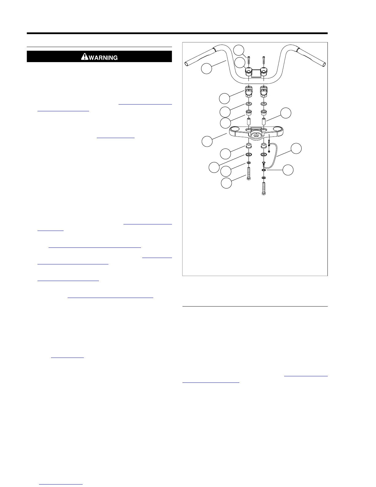
14. See Figure 2-104. Remove upper handlebar clamp
fasteners (1) and upper handlebar clamp (2). Remove
handlebar.
15. If removing lower handlebar clamps (4), remove two lower
handlebar clamp fasteners (10), lockwashers (9), ground
cable (12) and ground cable washer (11) and lower
handlebar clamps from upper fork bracket (8). Replace
bushings (6) if necessary.
1. Upper handlebar clamp fastener (4)
2. Upper handlebar clamp
3. Handlebar
4. Lower handlebar clamp (2)
5. Cup washer (4)
6. Bushing (4)
7. Spacer (2)
8. Upper fork bracket
9. Lockwasher (2)
10. Lower handlebar clamp fastener (2)
11. Ground cable washer (right side only)
12. Ground cable (right side only)
Figure 2-104. Handlebars: FXDWG/FXDF (FXDWG shown)
INSTALLATION
NOTE
The turn signal wires enter the switch housings through a relief
grommet in the housing. The turn signals must be supported
throughout this procedure to prevent pulling the grommet or
the turn sign wires out of the housing.
1. Repair or replace switches, turn signal switches, wires
and grommets as necessary.
NOTE
For handlebar switch repair procedures, see 8.28 HANDLEBAR
SWITCH ASSEMBLIES.
2. Wrap wire ends and open ends of conduit with electrical
tape.
3. Cut a length of mechanics wire to use as a leader.
4. Lay mechanics wire along the wire harnesses so a few
inches overlap and secure using electrical tape.
2-72 2008 Dyna Service: Chassis



 To Next Page