3.3ENGINE OIL FLOW
OIL FEED
NOTE
The oiling system is carefully designed for optimum efficiency.
All oil holes and passageways are specially sized. Exercise
caution to avoid enlarging oil holes during cleaning. Any
modification of the oiling system will adversely affect oil pres-
sure or cooling and lubrication efficiency.
See Figure 3-1. Oil flows from the oil pan (1) through a pas-
sageway at the front of the transmission housing (2).
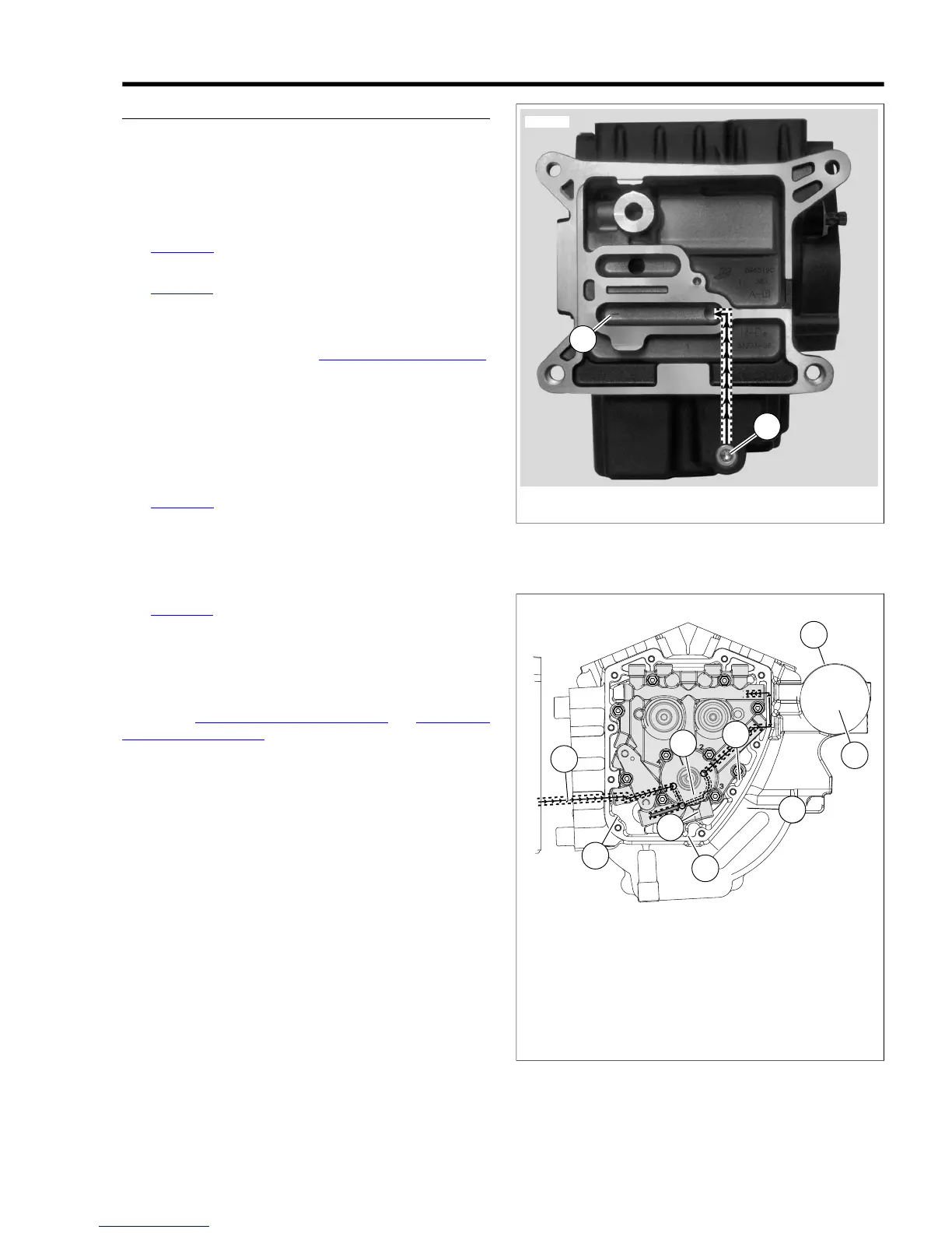
See Figure 3-2. Running through a passageway in the crank-
case (1), oil exits a hole in the crankcase flange and enters a
hole on the inboard side of the cam support plate (2). Passing
through a channel in the cam support plate, the oil enters the
feed side of the oil pump (3). See 3.4 OIL PUMP OPERATION.
The feed gerotors of the pump direct the flow up a second
channel in the cam support plate.
A passage (5) connects to a pressure relief valve (6) mounted
in the bypass port of the cam support plate. When the oil
pressure exceeds the setting of the valve spring (35 PSI), the
orifice opens to bypass (7) excess oil back to the feed side of
the pump (3).
See Figure 3-3. Oil not returned to the feed side exits a hole
on the inboard side of the cam support plate and passes
through a hole in the crankcase flange. Flowing through a
passageway in the crankcase, where a reading is taken by the
oil pressure sending unit (8), the oil exits the lower hole in the
oil filter mount.
See Figure 3-2. After circulating through the oil filter, the flow
of oil is directed back into the crankcase through the upper
hole in the oil filter mount. Exiting a passageway in the crank-
case through a hole in the crankcase flange, the flow of oil
reenters the cam support plate (9).
Filtered oil is then routed to the top and bottom ends of the
engine. See 3.3 ENGINE OIL FLOW, Top End and 3.3 ENGINE
OIL FLOW, Bottom End which follow.