5.2STARTER
GENERAL
The starter is made up of an armature, field winding assembly,
solenoid, drive assembly, idler gear and drive housing.
NOTE
For troubleshooting and diagnostic information, see the elec-
trical diagnostic manual for this motorcycle.
Starter Relay
The starter relay is not repairable. Replace the unit if it fails.
Wiring Diagrams
The starting circuit wiring diagram contains information about
wiring configuration. For additional information, see the elec-
trical diagnostic manual for this motorcycle.
REMOVAL
To prevent accidental vehicle start-up, which could cause
death or serious injury, disconnect negative (-) battery
cable before proceeding. (00048a)
1. Remove battery. See 1.17 BATTERY MAINTENANCE.
2. Remove battery tray. See 8.8 BATTERY TRAY AND
BATTERY CABLES.
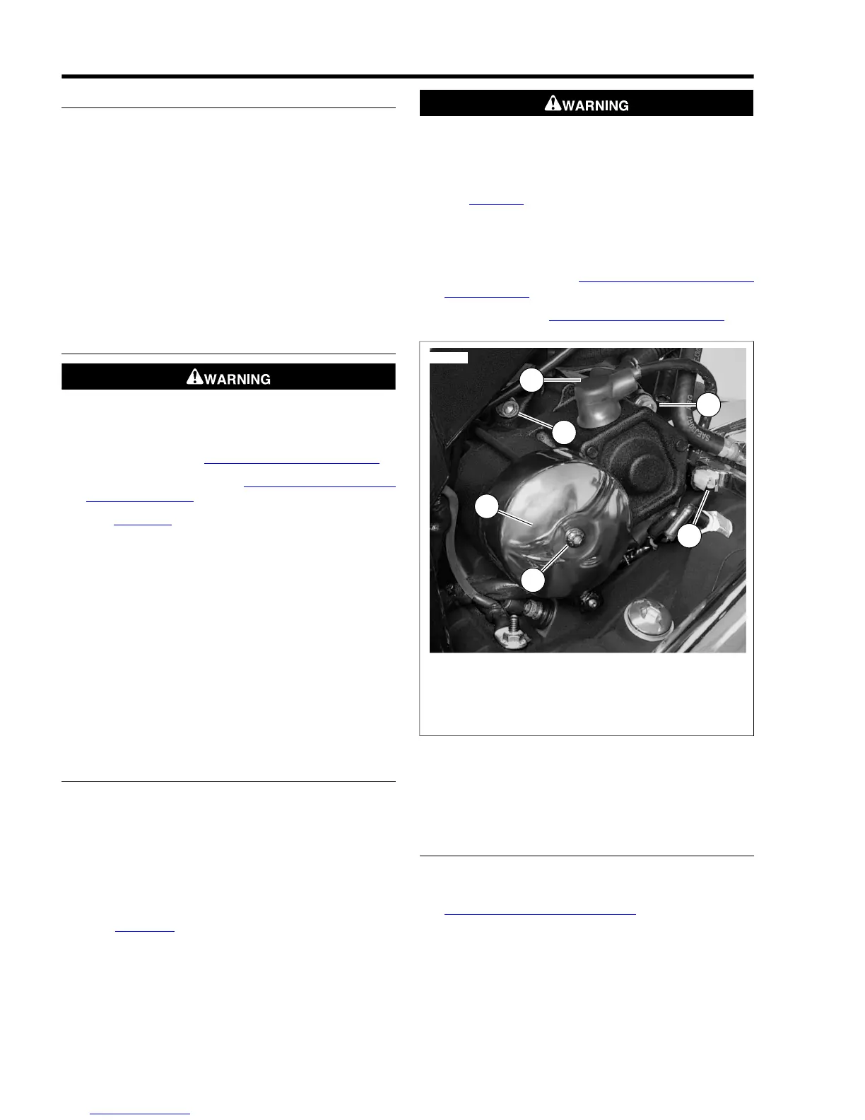
3. See Figure 5-1. Remove starter cover fastener (1) and
starter cover (2) from starter.
4. Disconnect starter wiring:
a. Remove protective boot (4).
b. Remove nut with washer (metric).
c. Remove positive battery cable ring terminal.
d. Detach solenoid wire (5).
5. Remove both starter mounting bolts and washers (3).
6. Remove starter from right side of motorcycle.
7. Discard starter housing O-ring.
8. Before disassembling the starter, perform diagnostics.
INSTALLATION
1. Examine two split ring dowel bushings in inner primary
housing where starter motor assembly mounts. If dowel
bushings are loose, remove bushings and pry open slightly
to provide an interference fit in primary housing. Reinstall
bushings into primary housing.
2. Install new starter housing O-ring.
3. Install starter from right side of motorcycle.
4. See Figure 5-1. Apply a drop of LOCTITE THREAD-
LOCKER 243 (blue) to threads of starter mounting bolts
(3).
5. Install the two starter mounting bolts (3) and washers.
Tighten to 25-27 ft-lbs (33.9-36.6 Nm).
Be sure rubber boot covers starter solenoid terminal
connected to positive (+) battery cable. An uncovered
terminal can short and cause sparks, which could result
in a battery explosion and death or serious injury. (00463c)
6. See Figure 5-1. Attach positive battery cable, and solenoid
wire (5).Tighten nut (metric) to 65-85 in-lbs (7.3-9.6 Nm).
Place protective boot (4) securely over terminal.
7. Attach starter cover (2) using fastener (1).
8. Install battery tray. See 8.8 BATTERY TRAY AND BAT-
TERY CABLES.
9. Install battery. See 1.17 BATTERY MAINTENANCE.
1. Starter cover fastener*
2. Starter cover*
3. Starter mounting fasteners
4. Protective boot
5. Solenoid wire
Figure 5-1. Starter
NOTE
Items marked with an asterisk (*) not used on all models.
TESTING
Armature
1. Remove armature and brush holder from field coil. See
5.2 STARTER, Field Coil Assembly.
2. Place armature in lathe or truing stand and check runout
of commutator. Commutators with more than 0.015
in. (0.38 mm) of runout should be replaced or machined
on a lathe. Commutators should be replaced when dia-
meter is less than 1.141 in. (29.98 mm).
5-2 2008 Dyna Service: Starter



 To Next Page