4. Thoroughly clean the oil pan with solvent.
5. Inspect preformed transmission top cover vent hose for
nicks, cuts or general deterioration. Replace as necessary.
Use low-pressure compressed air to verify that hose and
fitting are unobstructed.
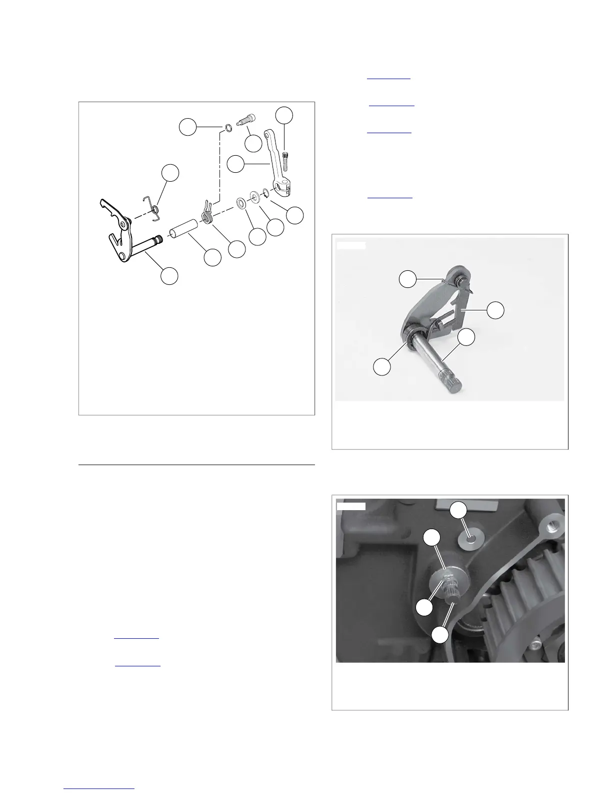
1. Shifter pawl lever assembly
2. Sleeve (inside transmission case)
3. Shift lever centering spring
4. Shifter shaft lever spring
5. Seal
6. Washer
7. Retaining ring
8. Screw
9. Shifter rod lever
10. Washer
11. Screw
Figure 7-55. Shifter Arm Assembly
ASSEMBLY
Countershaft Needle Bearing Replacement
1. Find a suitable bearing driver 1.25 in. (31.75 mm) in dia-
meter.
2. From the outside of the transmission case place the needle
bearing open end first next to the bearing bore. Hold the
driver squarely against the closed end of the bearing and
tap the bearing into place. The bearing is properly posi-
tioned when it is driven inward flush with the outside sur-
face of the case or to a maximum depth of 0.030 in. (0.76
mm).
3. Lubricate the bearing with transmission lubricant.
Shifter Pawl Lever Assembly
1. See Figure 7-55. Verify that sleeve (2) is inside transmis-
sion case.
2. See Figure 7-56. Slide shifter lever centering spring (3)
over shaft of shifter pawl lever assembly (2). Align opening
on spring with tab on lever.
3. Place shifter shaft lever spring (4) on shifter pawl lever
assembly.
NOTE
Do not bend shifter shaft lever spring more than necessary for
assembly.
4. See Figure 7-57. Insert the assembly into the transmission
case.
5. See Figure 7-58. Verify that pin sits inside shifter shaft
lever spring.
6. See Figure 7-57. Install a new seal. Install washer (1) and
a new retaining ring (2).
NOTE
In next step, shifter rod lever must be installed so angle of lever
is toward front of vehicle, one spline from vertical.
7. See Figure 7-55. Install shifter rod lever (9) on the shifter
pawl lever assembly shaft end using screw (8). Tighten
to 18-22 ft-lbs (24.4-29.8 Nm).
1. Pawl (part of shifter pawl lever assembly)
2. Shifter pawl lever assembly
3. Shifter lever centering spring
4. Shifter shaft lever spring
Figure 7-56. Shifter Pawl Lever Assembly
 Loading...