EasyManua.ls Logo

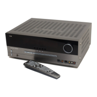
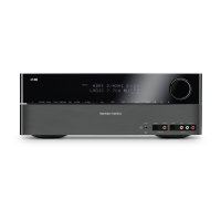
Harman Kardon AVR 347/230

Harman Kardon AVR 347/230
95 pages
To Next Page IconTo Next Page
Loading...
harman/kardon Service Manual
AVR 347/230
AVR 350/230
7 x 55W 7.1 CHANNEL A/V RECEIVERS
CONTENTS
ESD WARNING 2
BASIC SPECIFICATIONS 3
TROUBLESHOOTING GUIDE 4
PROCESSOR RESET 4
AVR 347 PACKAGE LIST AND PARTS 5
AVR 347 DISASSEMBLY 6
AVR 347 DISASSEMBLY PROCEDURE 7
AVR347 EXPLODED VIEW AND PARTS 11
AVR350 PACKAGE LIST AND PARTS 12
AVR 350 DISASSEMBLY 13
AVR 350 EXPLODED VIEW AND PARTS 14
ELECTRICAL PARTS LIST 15
PCB DRAWINGS 74
BLOCK DIAGRAM 83
WIRING DIAGRAM 84
AMP BIAS ADJUSTMENT 85
SCHEMATIC DIAGRAMS 86
(For Semiconductor Pinouts, see separate file )
Released EU2008 harman/kardon, Inc. Rev 0, 07/2008
250 Crossways Park Dr.
Woodbury, New York, 11797
harman/kardon
AVR 347/230 - AVR 350/230 Service Manual
Page 1 of 95
Question and Answer IconNeed help?

Do you have a question about the Harman Kardon AVR 347/230 and is the answer not in the manual?

Harman Kardon AVR 347/230 Specifications

General IconGeneral
BrandHarman Kardon
ModelAVR 347/230
CategoryReceiver
LanguageEnglish

Summary

Safety and Handling Procedures

Electrostatic Discharge (ESD) Precautions

Guidelines to prevent damage to sensitive components from static electricity.

Product Safety Notices

Crucial safety information for servicing and component replacement.

Technical Specifications

Audio, Tuner, and Video Specifications

Detailed performance parameters for audio, FM/AM tuners, and video sections.

General Unit Specifications

Power requirements, dimensions, and weight of the receiver.

Troubleshooting and Maintenance

Troubleshooting Common Issues

Symptom-based guide for diagnosing and resolving operational problems.

Processor Reset Procedure

Steps to reset the system memory and restore factory default settings.

Disassembly and Parts Identification

AVR347 Disassembly Procedures

Detailed steps for disassembling the AVR347 unit and its sub-assemblies.

AVR347 Exploded View and Parts

Visual parts breakdown and identification for the AVR347 model.

AVR350230 Disassembly Steps

Instructions for dismantling the AVR350/230 unit.

AVR350230 Exploded View and Parts

Visual parts breakdown and identification for the AVR350/230 model.

Electrical Parts List

Comprehensive list of all electrical components with part numbers and descriptions.

Diagrams and Adjustments

System Block Diagram

High-level overview of the unit's architecture and signal flow.

System Wiring Diagram

Diagram illustrating internal wiring connections between PCBs and components.

Amplifier Bias Adjustment Procedure

Procedure and target values for setting amplifier bias levels.

Main Schematic Diagram

Detailed schematic of the main PCB assembly, showing component interconnections.
Related product manuals