EasyManua.ls Logo

Harman Kardon DC5300 - Advanced Controls and Indicators; Bias Adjustment and Music Search; Copying and Recording Modes

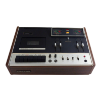
Harman Kardon DC5300
55 pages
To Next Page IconTo Next Page
To Previous Page IconTo Previous Page
Loading...
DISASSEMBLY
PROCEDURES
(REFER
TO
PAGE
9,
10
and
11)
[1]
TOP
COVER
(133)
REMOVAL
Remove
4screws
(A)
and
2
screws
(B),
andthen
remove
the
Top
Cover(133).
FRONT
PANEL
ASSEMBLY
(AA)
REMOVAL
1.
Remove
the
Top
Cover
(133).
2.
Disconnect
1
connector
(JL901)
from
(CN904)
on
the
Main
P.
C.
Board
(PCB-1).
3.
Remove
6
screws
(C)
and
3
screws
(D),
and
the
remove
the
Front
Panel
Assembly
(AA).
4.
If
necessary,
unsolder
the
lead
wires.
CASSETTE
TAPE
RECORDER
MECHANISM
ASSEMBLY
(103)
REMOVEL
1.
Remove
the
Front
Panel
Assembly
(AA).
(Refer
to
Step
2.)
2.
Disconnect
4
connectors
(LCN101/351,
LCN801,
LCN802
and
LCN803)
on
the
Primary
Transport
P.
C.
Board
(103).
3.
Remove
4-screws
(E),
and
then
the
Cassette
Tape
Recorder
Mechanism
Assembly
(103).
[4|
CASSETTE
TAPE
PLAYER
MECHANISM
ASSEMBLY
(104)
REMOVAL
1.
Remove
the
Front
Panel
Assembly
(AA).
(Refer
to
Step
2).
2.
Disconnect
4
connectors
(LCN151,
LCN806,
LCN807
and
LCN808)
on
the
Secondary
Transport
P.
C.
Board
(104).
3.
Remove
4
screws
(F),
and
then
the
Cassette
Tape
Player
Mechanism
Assembly
(104).
[5]
MAIN
P.
C.
BOARD
(PCB-1)
REMOVAL
1.
Remove
the
Front
Panel
Assembly
(AA).
(Refer
to
step
2).
2.
Disconnect
4
connectors
(LCN151,
LCN806,
LCN807
and
LCN808)
onthe
Secondary
TransportP.
C.
Board
(103).
3.
Disconnect
4
connectors
(LCN101/351,
LCN801,
LCN802
and
LCN803)
on
the
Primary
Transport
P.
C.
Board
(104).
4.
Disconnect
5
Jumper
Leads
(JL1,
JL2,
JL3,
JL4
and
JL5)
from
5connectors
(CN805,
CN804,
CN803,
CN802
and
CN801)
on
the
Power
P.
C.
Board
(PCB-4).
5.
Remove
9
screws
(G),
1
screw
(H)
and
2
screws
(I)
and
then
remove
the
Main
P.
C.
Board
(PCB-1).
POWER
P.
C.
BOARD
(PCB-4)
REMOVAL
1.
Remove
the
Front
Panel
Assembly
(AA).
(Refer
to
step
2).
:
2.
Disconnect
5
Jumper
Leads
(JL1,
JL2,
JL3,
JL4
and
JL5)
on
the.
Power
P.
C.
Board
(PCB-4).
3.
Disconnect
3
connectors
(LCN801,
LCN802
and
LCN803)
on
the
Primary
Transport
P.
C.
Board.
4.
Remove
5
screws
(J)
and
4
screws
(K),
and
then
remove
the
Power
P.
C.
Board
(PCB-4).
OTHER
P.C.
BOARDS
REMOVAL
1.
Remove
the
Front
Panel
Assembly
(AA).
(Refer
to
step
2).
2.
Remove
4
screws
(L),
and
then
remove
the
Cont
SW-L
P.
C.
Board
(PCB-7).
3.
Remove
3
screws
(M),
and
then
remove
the
Cont
SW-R
P.
C.
Board
(PCB-6).
4.
Remove
3
Rotary
Knobs
(146)
and
3
screws
(N),
and
then
remove
the
Volume
P.
C.
Board
(PCB-2).
5.
Remove
7
screws
(O),
and
then
remove
the
Front
P.
C.
Board
(PCB-5).
POWER
CORD
REPLACEMENT
(FOR
SERVICE
ENGINEERS
OTHER
THAN
NORTH
AMERICA)
In
order
to
prevent
fire
shock
hazard
when
replacing
the
power
cord,
follow
the
Procedure
below
to
replace
the
part
with
the
standard
supply
parts.
Pi
POWER
CORD
Ba]
rt
HOLDER
11
POWER
TRANSFORMER
BLUE
PCB-4
CABINET
BACK
100mm
MAX.
8mm

Other manuals for Harman Kardon DC5300

Related product manuals