Do you have a question about the Harman Kardon TD202 and is the answer not in the manual?
Controls the unit's power ON/OFF state.
Illuminates when the unit is powered ON.
Opens the cassette compartment door slowly.
Compartment for inserting and housing cassette tapes.
Resets the tape counter display to zero.
Digital display indicating tape position for cueing.
Selects recording/playback circuitry for different tape types.
Rewinds the tape at high speed.
Sets record standby or temporarily stops recording.
Indicates when the unit is actively recording.
Initiates tape playback operation.
Shows that the tape playback is currently active.
Stops all playback, recording, and transport operations.
Advances the tape quickly in the playback direction.
Creates silent segments during recording by holding button.
Displays the signal level during recording or playback.
Activates or deactivates the Dolby Noise Reduction system.
Selects between Dolby B or C type noise reduction.
Illuminates when Dolby NR is active.
Allows precise adjustment of recording bias during use.
Filters FM stereo pilot signal frequencies during recording.
Adjusts the recording level for input audio signals.
Procedure for removing the top cabinet cover.
Step-by-step guide to remove the front panel assembly.
Instructions for removing the main printed circuit board.
Steps for detaching the display printed circuit board.
Guide to removing the function switches PCB.
Description of the playback signal path for the TD102 model.
Description of the recording signal path for the TD102 model.
Description of the playback signal path for the TD202 model.
Description of the recording signal path for the TD202 model.
Explains the logic operations during record mode for TD102.
Describes mode switching logic from record to playback for TD102.
Explains the logic operations during record mode for TD202.
Describes mode switching logic from record to playback for TD202.
Details the muting function during operation mode changes.
Verifies cassette mechanism functions before alignment procedures.
Outlines electrical checks and adjustments needed for optimal performance.
Guides on adjusting head azimuth for proper playback.
Layout and component placement for the main PCB.
Layout for the display PCB.
Layout for the power supply PCB.
Layout for the control switches PCB.
Layout for the function switches PCB.
Layout for the power indicator PCB.
Schematic for the playback amplifier circuits.
Schematic for Dolby NR and MPX filter circuits.
Schematic for the peak level meter indicators.
Schematic of the unit's power supply section.
Schematic details for bias and equalization circuits.
Schematic for the recording amplifier circuits.
Schematic of the logic control circuitry for operation.
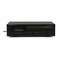
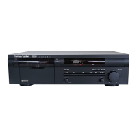
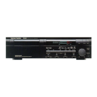
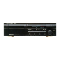
| Brand | Harman Kardon |
|---|---|
| Model | TD202 |
| Category | Cassette Player |
| Language | English |