SINGLE-PHASE BRIDGE RECTIFIER
DF005 THRU DF10
VOLTAGE RANGE 50 to 1000 Volts
DB101 THRU DB107
CURRENT 1.0 Ampere
FEATURES
• Glass passivated chip junction
• High forward surge current capability
• Ideal for printed circuit board
• High temperature soldering guaranteed:
260℃/10 seconds at terminals
MECHANICAL DATA
• Case: Transfer molded plastic
• Epoxy: UL94V-0 rate flame retardant
• Terminals solderable per MIL-STD-202E
method 208C
• Polarity: Molded on body
• Mounting position: Any
• Weight: 0.04 ounce, 1.0 gram
MAXIMUM RATINGS AND ELECTRICAL CHARACTERISTICS
• Ratings at 25℃ ambient temperature unless otherwise specified
• Single Phase, half wave, 60Hz, resistive or inductive load
• For capacitive load derate current by 20%
SYMBOLS
DF005
DB101
DF01
DB102
DF02
DB103
DF04
DB104
DF06
DB105
DF08
DB106
DF10
DB107
UNIT
Maximum Reverse Peak Repetitive Voltage
V
RRM
50 100 200 400 600 800 1000
Volts
Maximum RMS Voltage
V
RMS
35 70 140 280 420 560 700 Volts
Maximum DC Blocking Voltage
V
DC
50 100 200 400 600 800 1000
Volts
Maximum Average Forward Rectified Output
Current, 0.06”(1.5mm) lead length at T
A
=40℃
(Note 2)
I
(AV)
1.0 Amps
Peak Forward Surge Current
8.3ms single half sine wave superimposed on
rated load (JEDEC Method)
I
FSM
50 Amps
Rating for Fusing (t<8.3ms)
I
2
t 10 A
2
s
Maximum Instantaneous Forward Voltage drop
Per Bridge element 1.0A
V
F
1.1 Volts
TA=25℃
5
µAmps
Maximum Reverse Current at rated
DC blocking voltage per element
TA=125℃
I
R
0.5
mAmps
Typical Junction Capacitance (Note 1)
C
J
25
pF
Typical Thermal Resistance (Note 2)
R
ΘJA
40
℃/W
Operating and Storage Temperature Range
T
J
,T
STG
-55 to +150
℃
Notes: 1. Measured at 1.0MHz and applied reverse voltage of 4.0 Volts.
2.Unit mounted on P.C.B. with 0.51”×0.51” ( 13×13mm) copper pads.
~
~
+
-
Dimensions in inches and (millimeters)
DFM
.245 (6.2)
.255 (6.5)
.195 (5.0)
.205 (5.2)
(0.5)
.020
(1.5)
.060
.300 (7.6)
.350 (8.9)
.155 (3.9)
.165 (4.2)
.115 (2.9)
.135 (3.4)
.320 (8.12)
.365 (9.3)
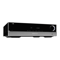
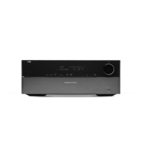
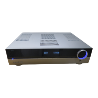
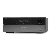
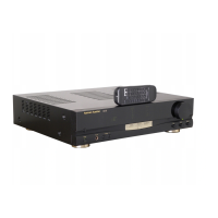
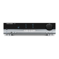
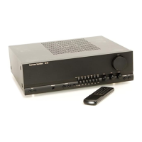
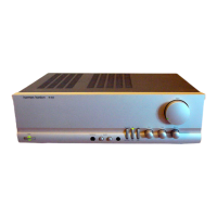
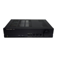
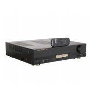
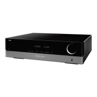
HK 980/230 Service Manual
 Loading...