EasyManua.ls Logo

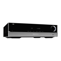
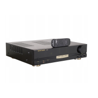
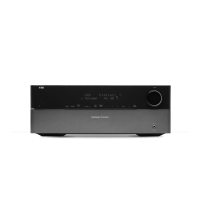
Harman Kardon HK1400 - User Manual

Harman Kardon HK1400
24 pages
To Next Page IconTo Next Page
Loading...
The
Harman
Kardon
Model
HK1200/HK1400
sient
STEREO
LINE
AMPLIFIER
echnical
Manual
harman“‘kardon
HK1400
)
one
O
The
following
marks
found
in
the
parts
list
of
this
manual
identify
the
models
as
follows.
:
North
America
area
model
Black
version
@
:
International
model
Black
version
UD
:
Asia/Oceania
model
Black
version
CONTENTS
SPECIFICATIONS
eee
2
GENERAL
UNIT
PARTS
LIST
.....eessssseeseeees
6
LEAKAGE
TEST
voces
v2
GENERAL
UNIT
vceccstsesecsestesesssseseeserseaneene
7
DISASSEMBLY
PROCEDURES...
+3
P.C.
BOARDS.......
8,
15,
16
POWER
CORD
REPLACEMENT
..
3
>
ELECTRICAL
PARTS
LIST
9,11,
17
CONTROLS
AND
FUNCTIONS
...
4
SCHEMATIC
DIAGRAMS
...
10,
13,
19
ALIGNMENT
PROCEDURES...
5
WIRING
DIAGRAM
....
ecesessssecscseseeee
14,
20
BLOCK
DIAGRAM
oo
ceecsetesraresesenseeeseteeee
5
harman/kardon
Parts
and
Service
Office
240
Crossways
Park
West,Woodbury,N.¥.
11797
1112-0530A152
G9310
1500
Printed
in
Japan
00%LMH/00ZLMH
Question and Answer IconNeed help?

Do you have a question about the Harman Kardon HK1400 and is the answer not in the manual?

Harman Kardon HK1400 Specifications

General IconGeneral
BrandHarman Kardon
ModelHK1400
CategoryAmplifier
LanguageEnglish

Summary

Specifications

Disassembly Procedures

Cabinet Top (AB) Removal

Procedure to remove the top cabinet part.

Main P. C. Board (PCB-1) Removal

Procedure to remove the main circuit board.

Power Cord Replacement

Controls and Functions

Power Switch

Description of the power switch operation.

Source Selector

Function of the source selector.

Volume Control

Description of the volume control knob.

Alignment Procedures

DC Balance Adjustment

Procedure for adjusting DC balance.

Idling Current Adjustment

Procedure for adjusting idling current.

Block Diagram

General Unit Parts List

General Unit Exploded View

P. C. Boards (1)

PCB-5 AC Outlet P.C. Board

Details for the AC outlet circuit board.

PCB-2 Bias (L) P.C. Board

Details for the left bias circuit board.

PCB-6 SP Terminal P.C. Board

Details for the speaker terminal circuit board.

PCB-4 Pre Amp P.C. Board

Electrical Parts List

PCB-2 Bias (L) P.C. Board

Electrical parts for the left bias circuit board.

PCB-4 Pre Amp P.C. Board

Electrical parts for the pre-amplifier circuit board.

PCB-5 AC Outlet P.C. Board

Electrical parts for the AC outlet circuit board.

Abbreviations in Parts List

Electrical Parts List (Model: HK1200)

Schematic Diagram (1)

PCB-4 Pre Amp P.C. Board

Schematic diagram for the pre-amplifier circuit board.

Schematic Diagram (2) (Model: HK1200)

PCB-1 Main Amp P.C. Board

Schematic for the main amplifier circuit board.

PCB-2 Bias (L) P.C. Board

Schematic for the left bias circuit board.

PCB-3 Bias (R) P.C. Board

Schematic for the right bias circuit board.

Schematic Diagram (2) (Model: HK1400)

PCB-1 Main P.C. Board

Schematic for the main amplifier circuit board.

PCB-2 Bias (L) P.C. Board

Schematic for the left bias circuit board.

PCB-3 Bias (R) P.C. Board

Schematic for the right bias circuit board.

Wiring Diagram (Model: HK1200)

PCB-12 Volt Select P.C. Board

Wiring for the volt select circuit board.

PCB-5 AC Outlet P.C. Board

Wiring for the AC outlet circuit board.

PCB-8 Power P.C. Board

Wiring for the power circuit board.

Wiring Diagram (Model: HK1400)

PCB-12 Volt Select P.C. Board

Wiring for the volt select circuit board.

PCB-5 AC Outlet P.C. Board

Wiring for the AC outlet circuit board.

PCB-8 Power P.C. Board

Wiring for the power circuit board.

Related product manuals