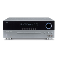
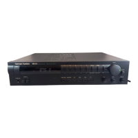
Do you have a question about the Harman Kardon HK3380 and is the answer not in the manual?
| Total Harmonic Distortion | 0.07% |
|---|---|
| Input Sensitivity | 200mV |
| Speaker Load Impedance | 8 ohms |
| Tuning Range | FM, AM |
| Power Output | 80 watts per channel |
| Inputs | 1 phono |
| Outputs | 1 subwoofer |
Important safety precautions for servicing and component replacement.
Details audio performance parameters like power, sensitivity, and frequency response.
Specifies FM tuner performance metrics such as frequency range and sensitivity.
Lists AM tuner specifications, including frequency range and sensitivity.
Outlines video input/output specifications and frequency response.
Covers power requirements, dimensions, and weight of the unit.
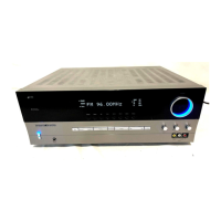
Controls for unit power, status indicators, and headphone output.
Buttons for selecting audio sources like Phono, CD, Tape, and Video inputs.
Controls for radio tuning, presets, and FM modes.
Adjustments for bass, treble, balance, and master volume.
Controls for speaker output selection and sleep timer.
Controls for display dimming and remote sensor window.
Indicators for speaker selection and selected input source.
Indicators for tuner status, presets, and memory operations.
Indicators for mute status, stereo reception, and auto mode.
Ports for audio sources, recorders, and video devices.
Antenna inputs and remote control ports.
Speaker terminals and AC power input.
Controls for powering the unit and selecting input sources.
Buttons for tuning, presets, and radio mode selection.
Controls for transport, sleep, dimming, and muting functions.
Numeric keypad and direct input buttons for station selection.
Controls for speaker selection and memory storage.
Troubleshooting steps for no power or no sound problems.
Diagnosing tuner interference, distortion, and input signal problems.
Troubleshooting remote control and processor reset procedures.
Specifies conditions, standard values, and voltmeter connections for bias adjustment.
Addresses erratic volume control tracking and display issues on early units.
Addresses silence during preset scan, requiring a software upgrade.
Procedures for removing the outer cabinet and front panel assembly.
Steps for removing the rear panel and main PCB.
Detailed steps for removing Tone, Phone, Power LED, Front, and Tuner PCBs.
Steps for removing Video, Download, Power Trans, and Main PCB assemblies.
Exploded view of the unit's exterior parts.
Exploded view of internal assemblies like PCBs and modules.
Block diagram illustrating tuner and audio signal flow.
Block diagram showing video and power signal routing.
Details the physical size and measurements of the unit.
Table detailing pin assignments and connections.
Illustrates the layout and patterns for the front panel display segments.
Specifies the illumination color for front panel indicators.
Maps front panel display segments to functions.
Illustrates the internal architecture of the HVIST72F321R IC.
Diagram showing pin assignments for the 64-pin TQFP package.
Comprehensive list of pins, types, ports, and alternate functions.
Illustrates the EEPROM's internal structure and signal definitions.
Details pin assignments for DIP, SO, and TSSOP packages.
Overview of the NJM2068 amplifier's features and performance.
Shows package types and pin assignments for the NJM2068.
Schematic of the internal equivalent circuit for half the amplifier.
Illustrates the block diagram for the NJM2296M IC.
Shows the pinout and function of IC92.
Outlines the pinout and functional description of the reset IC.
Presents the internal block diagrams for the IC84.
Shows the IC85 block diagram and timing characteristics.
Defines the tPLH parameter for output delay.
Shows the internal structure and signal flow of the TC9164AF IC.
Shows the internal structure and signal flow of the TC9163AF IC.
Details the input/output paths and decoding logic.
Describes the shift register and level shifting circuits.
Describes Vss, Vdd, and GND pin functions.
Details the input and output pins for volume control.
Describes pins related to the loudness tap output.
Explains chip select, clock, and data input pins.
Identifies pins designated for no connection.
Shows block diagrams for TO-92M and TO-126 transistor packages.
Shows block diagrams for TO-3P and TO-220 transistor packages.
Shows block diagrams for common regulator ICs.
Lists capacitors, semiconductors, and resistors for the front PCB.
Lists capacitors, semiconductors, and resistors for the main PCB.
Lists miscellaneous parts, fuses, and tuner module information.
Diagram showing component placement on the front PCB.
Diagram showing component placement on the main PCB.
Diagrams showing component placement on Tone and Video PCBs.
Circuit diagram for the tuner section and audio inputs.
Circuit diagram for video, control, and power supply sections.
Circuit diagram for power amplifier stages and protection.
Diagrams for download, RDS, and transformer connections.
Circuit diagram for microcontroller, EEPROM, and analog controls.
Circuit diagram for tuner control and volume/tone circuits.
Wiring diagram for power supply and main PCB connections.
Wiring diagram for front, video, and tuner module connections.
Lists items included with the product, such as manuals and cables.
Illustrates the product packaging and its contents.


 Loading...