EasyManua.ls Logo

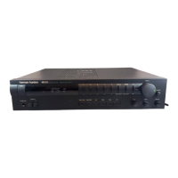
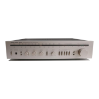
Harman Kardon HK3400 User Manual

Harman Kardon HK3400
36 pages
To Next Page IconTo Next Page
Page #1 background imageLoading...
Page #1 background image
The
Harman
Kardon
Model
HK3400
Manual
1688
STEREO
RECEIVER
yechnicall
IManua
This
manual
is
to
be
applied
to
the
North
America
area
model
with
serial
number
S189-04202
and
above,
and
International
and
Australia
models.
The
following
marks
found
in
the
parts
list
of
this
manual
identify
the
models
as
follows.
:
North
America
area
model
Black
version
:
International
model
:
International
model
Black
version
:
Australia
model
Black
version
CONTENTS
SPECIFICATIONS
ccceesececccccerececeeeceseeteceeeaeesesteneeeseseeeas
2
ALIGNMENT
PROCEDURES
igre
egies
8
CPE
AKAGE
TEST
sssarstetetesiestiad
uw
ara
ea
eeioca
seals
3
GENERAL
UNIT
POWER
CORD
REPLACEMENT
-
vr
rccccecrerercceteeeesessereeeerees
3
(EXPLODED
VIEW.
PARTS
LIS
F)itssseteterne
acess
Siteanct
ena
9
CONTROLS
&
FUNCTIONS
vireccccceeeeeeecteteneeeeee
ee
ten
tes
ee
eens
4
WIRING
DIAGRAM
=
rtsessress
teeeererrseeses
torr
ee
scertinin
scene
12
DISASSEMBLY
PROCEDURES
«-rvvesesesceceeeeeeeseseeteeeeeeeees
5
PC
BOARD
Sites
ieee
caie
eee
eee
eet
14
CIRCUIT
DESCRIPTION
cocccccceceecccererceeeete
ee
eeeee
tee
eeneeeeeees
6
BEECTRICAL
PARTS:
LIS.
setter
seem
cetaicsertenta
hoes
tnertarias
18
BLOCK
DIAGRAM
cocvecccececececrerrece
erence
tenes
eet
ne
neta
nee
ea
nnns
7
IC
BLOCK
DIAGRAM/IC
TERMINAL
FUNCTIONS
-::::-------
25
TIMING
CHART
ceccereesccceceteceeeceseteeeteeecenessseseeaneaeereaaennes
7
SCHEMATIC
DIAGRAM:
6232s
ee
tee
totes
reeset
ren
enietens-
26
harman/kardon
240
Crossways
Park
West,
Woodbury,
N.Y.
11797
1112-3152168B1
P-079106
2000
Printed
in
Japan
Question and Answer IconNeed help?

Do you have a question about the Harman Kardon HK3400 and is the answer not in the manual?

Harman Kardon HK3400 Specifications

General IconGeneral
Frequency response10Hz - 100kHz (+0.5dB, -3dB)
Input sensitivity (MM)2.2mV
Input sensitivity (line)135mV
Signal to noise ratio (MM)80dB
Weight7.7kg
Tuning rangeFM

Summary

CONTENTS

SPECIFICATIONS

Detailed technical performance parameters of the receiver.

LEAKAGE TEST

Safety procedure for testing electrical leakage current before use.

POWER CORD REPLACEMENT

Procedure for replacing the power cord safely.

DISASSEMBLY PROCEDURES

Step-by-step instructions for disassembling various unit components.

ALIGNMENT PROCEDURES

Steps for calibrating and adjusting the receiver's performance parameters.

GENERAL UNIT (EXPLODED VIEW, PARTS LIST)

Exploded view and list of parts for the main unit assembly.

WIRING DIAGRAM

Diagrams showing electrical connections between various circuit boards.

P.C. BOARDS

Detailed layout diagrams of the various printed circuit boards.

ELECTRICAL PARTS LIST

Comprehensive list of all electronic components used in the receiver.

SPECIFICATIONS

FM SECTION

Performance specifications for the FM receiver section.

AM SECTION

Performance specifications for the AM receiver section.

AUDIO SECTION

Performance specifications for the audio amplification stages.

LEAKAGE TEST

LEAKAGE TEST (FOR SERVICE ENGINEERS IN THE U.S.A.)

Safety procedure for testing electrical leakage current before use.

POWER CORD REPLACEMENT

POWER CORD REPLACEMENT (FOR SERVICE ENGINEERS OTHER THAN NORTH AMERICA)

Procedure for replacing the power cord safely for non-North American models.

DISASSEMBLY PROCEDURES

Cabinet Top Removal

Steps to remove the main cabinet top cover.

Front Panel Assembly Removal

Steps to detach the front panel assembly.

Front P.C. Board Removal

Steps to remove the front panel printed circuit board.

Tone Control P.C. Board Removal

Steps to remove the tone control printed circuit board.

Volume P.C. Board Removal

Steps to remove the volume control printed circuit board.

Headphone P.C. Board Removal

Steps to remove the headphone jack printed circuit board.

Speaker Switch P.C. Board Removal

Steps to remove the speaker switch printed circuit board.

Power Switch P.C. Board Removal

Steps to remove the power switch printed circuit board.

Tuner P.C. Board Removal

Steps to remove the tuner printed circuit board.

Sub Woofer Board Removal

Steps to remove the subwoofer printed circuit board.

Speaker Terminal P.C. Board Removal

Steps to remove the speaker terminal printed circuit board.

Main P.C. Board Removal

Steps to remove the main printed circuit board.

Secondary P.C. Board Removal

Steps to remove the secondary printed circuit board.

ALIGNMENT PROCEDURES

Idling Current Adjustment

Procedure for adjusting the receiver's idling current.

AM Adjustment

Alignment procedures for the AM tuning and tracking.

FM Adjustment

Alignment procedures for FM discriminator, muting, and separation.

GENERAL UNIT PARTS LIST

GENERAL UNIT PARTS LIST (Continued)

GENERAL UNIT EXPLODED VIEW

WIRING DIAGRAM

WIRING DIAGRAM (Continued)

P.C. BOARDS

P.C. BOARDS (Continued)

ELECTRICAL PARTS LIST

ELECTRICAL PARTS LIST (Continued)

Related product manuals