<8>VIDEO PCB(43) REMOVAL
1. Remove the Top-cabinet, referring to the previous step<1>.
2. Disconnect the connector (CN91) on the Main PCB ASS’Y(44) from lead wire(BN91-9P)
on the Video PCB(43).
3. Remove 4 screws(S8,S13) and then remove the Video PCB(43).
<9>DOWNLOAD PCB(42) REMOVAL
1. Remove the Top-cabinet, referring to the previous step<1>.
2. Disconnect the connector (CN89) from lead wire(BN89-7P) on the Front PCB(37).
3. Remove 2 screws(S4) and then remove the Download PCB(42).
<10>POWER TRANS(30) REMOVAL
1. Remove the Top-cabinet, referring to the previous step<1>.
2. Disconnect the connector (CN62,CN63,CN64) on the Trans PCB from lead wire(BN62-2P,BN63-3P,BN64-6P)
on the Main PCB(44).
3. Remove 4 Trans screws(S9) and then remove the Power Trans(30).
<11>MAIN PCB ASS’Y(44) REMOVAL
1. Remove the Top-cabinet, referring to the previous step<1>.
2. Remove the Power Trans(30), referring to the previous step<10>.
3. Disconnect the connector(CN81-20P wire ass’y) from connector(CN81-7P) on the Front PCB(37).
4. Disconnect the connector(CN82) from lead wire(BN82-7P) on the Front PCB(37).
5. Disconnect the connector(CN71) from lead wire(BN71-12P) on the Tone PCB(38).
6. Disconnect the connector(CN72) from lead wire(BN72-5P) on the Tone PCB(38).
7. Disconnect the connector(CN73) from lead wire(BN73-3P) on the Phone PCB(40).
8. Disconnect the connector(CN91) from lead wire(BN91-9P) on the Video PCB(43).
9. Disconnect the connector(CN26-Card cable) from lead wire(CON1) on the Tuner Module(34).
10. Disconnect the connector(CN61) from Power cord(35).
11. Remove 21 screws(S8-11EA, S13-1EA, S4-2EA, S6-2EA, S15-1EA, S12-3EA, S5-1EA) and then
remove the Main PCB ASS’Y(44).
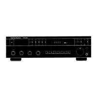
HK3480 harman/kardon
 Loading...