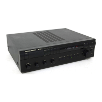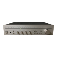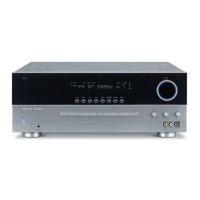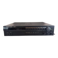
Do you have a question about the Harman Kardon HK3550 and is the answer not in the manual?
| Tuning range | FM, MW |
|---|---|
| Total Harmonic Distortion | 0.09% |
| Input Sensitivity | 2.5mV (MM), 150mV (line) |
| Speaker Load Impedance | 8Ω (minimum) |
| Power Output | 50 watts per channel into 8Ω (stereo) |
| Frequency Response | 10Hz to 100kHz |
Detailed specifications for the FM tuner section, including sensitivity, selectivity, and distortion.
Detailed specifications for the AM tuner section, including sensitivity and signal-to-noise ratio.
Detailed specifications for the audio amplifier section, including sensitivity and power output.
Explanation of the FM signal path, amplification, and conversion to intermediate frequency.
Explanation of the AM signal path, amplification, and detection.
Description of audio signal processing, pre-amplification, and power amplification.
Description of the circuit that mutes audio output under weak signal or tuning conditions.
Explanation of the PLL synthesizer's role in frequency control.
Explanation of how the frequency display and tuning indicators are controlled.
Steps for adjusting AM signal generator, IF, and tracking for optimal output.
Steps for aligning FM discriminator, muting level, and stereo separation.
Procedure to adjust DC balance in the power amplifier section.
Procedure to adjust idling current in the power amplifier section.
