EasyManua.ls Logo

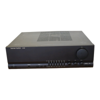
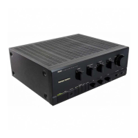
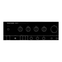
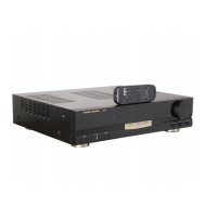
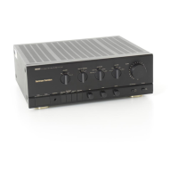
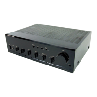
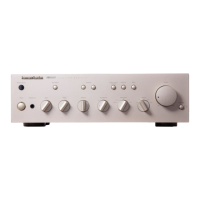
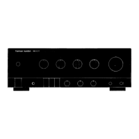
Harman Kardon HK680 - Controls and Functions Overview; Input Selection Controls; Volume and Tone Controls

Harman Kardon HK680
50 pages
To Next Page IconTo Next Page
To Previous Page IconTo Previous Page
Loading...
G
HK680
DISASSEMBLY
PROCEDURES
(REFER
TO
PAGES
7
AND
22)
[1]
CABINET
TOP
(131)
REMOVAL
Remove
8
screws
(A)
and
then
remove
the
Cabinet
Top
(131).
FRONT
PANEL
ASS’Y
(AA)
REMOVAL
1.
Remove
the
Cabinet
Top
(131),
referring
to
the
previous
step
[1].
2.
Pull
out
3
Rotary
Knobs
(151).
3.
Remove
5
screws
(B)
and
then
remove
the
Front
Panel
Ass‘y
(AA).
MAIN
AMP.
P.C.
BOARD
(PCB-1)
REMOVAL
1.
Remove
the
Front
Panel
Ass‘y
(AA),
referring
to
the
previous
step
[2].
2.
Disconnect
the
1
connector
(CW703)
from
1
connector
(CN703)
on
the
Input
Selector
P.C.
Board
(PCB-13).
.
Pull
out
the
Rotary
Knob
(150)
and
4
Push
Buttons
(146).
.
Disconnect
the
1
connector
(CW704)
from
1
connector
(CN704)
on
the
Volume
P.C.
Board
(PCB-11).
5.
Remove
4
screws
(C)
and
then
remove
the
Metal
Fitting
(165).
6.
Disconnect
the
2
connectors
(CW284
and
CW705)
from
2
connectors
(CN284
and
CN705)
on
the
Main
Amp.
P.C.
Board
(PCB-1).
7.
Remove
7
screws
(D)
and
then
remove
the
Main
Amp.
P.C.
Board
(PCB-1).
If
necessary
unsolder
the
lead
wire.
Pw
[4]
INPUT
SELECTOR
P.C.
BOARD
(PCB-13)
REMOVAL
1.
Remove
the
Cabinet
Top
(131),
referring
to
the
previous
step
[1].
2.
Disconnect
the
1
connector
(CW703)
from
1
connector
(CN703)
on
the
Input
Selector
P.C.
Board
(PCB-13).
3.
Disconnect
the
1
connector
(CW281)
from
1
connector
(CN281)
on
the
Power
Supply
P.C.
Board
(PCB-5).
4.
Disconnect
the
1
connector
(CW704)
from
1
connector
(CN704)
on
the
Volume
P.C.
Board
(PCB-11).
5.
Disconnect
the
1
connector
(CW705)
from
1
connector
(CN705)
on
the
Main
Amp.
P.C.
Board
(PCB-1).
Disconnect
the
2
connectors
(CW701
and
CW702)
from
2
connectors
(CN701
and
CN702)
on
the
Control
P.C.
Board
(PCB-12).
6.
Remove
8
screws
(E)
and
then
remove
Input
Selector
P.C.
Board
(PCB-13)
with
Power
LED
P.C.
Board
(PCB-
15).
[5]
VOLUME
P.C.
BOARD
(PCB-11)
REMOVAL
1.
Remove
the
Front
Panel
Ass‘y
(AA),
referring
to
the
previous
step
[2].
2.
Disconnect
the
connector
(CW703)
from
connector
(CN703)
on
the
Input
Selector
P.C.
Board
(PCB-13).
3.
Pull
out
the
Rotary
Knob
(150).
4.
Disconnect
the
1
connector
(CW704)
from
1
connector
(CN704)
on
the
Volume
P.C.
Board
(PCB-11).
5.
Remove
hexagon
nut
(F)
and
then
remove
the
Volume
P.C.
Board
(PCB-11).
[6]
TONE
CONTROL
P.C.
BOARD
(PCB-9)
REMOVAL
1.
Remove
the
Volume
P.C.
Board
(PCB-11),
referring
to
the
previous
step
[5].
2.
Disconnect
the
1
connector
(CW282)
from
1
connector
(CN282)
on
the
Tone
Control
P.C.
Board
(PCB-9).
3.
Disconnect
the
1
connector
(CW284)
from
1
connector
(CN284)
on
the
Main
Amp.
P.C.
Board
(PCB-1).
4.
Disconnect
the
1
connector
(CW203)
from
1
connector
(CN283)
on
the
Control
P.C.
Board
(PCB-12).
5.
Pull
out
2
Push
Buttons
(146).
6.
Remove
hexagon
nuts
(G),
3
screws
(H)
and
then
re-
move
Tone
Control
P.C.
Board
(PCB-9)
and
Mono/
Stereo
Switch
P.C.
Board
(PCB-10).
[7]
POWER
SUPPLY
P.C.
BOARD
(PCB-5)
REMOVAL
1.
Remove
the
Cabinet
Top
(131),
referring
to
the
previous
step
[1].
2.
Disconnect
2
connectors
(CW3
and
CW281)
from
2
connectors
(CN3
and
CN281)
on
the
Power
Supply
P.C.
Board
(PCB-5).
3.
Remove
2
screws
(1)
and
then
remove
Power
Supply
P.C.
Board
(PCB-5).
[8]
CONTROL
P.C.
BOARD
(PCB-12)
REMOVAL
1.
Remove
the
Main
Amp.
P.C.
Board
(PCB-1),
referring
to
the
previous
step
[3].
2.
Remove
7
screws
(J)
and
then
Control
P.C.
Board
(PCB-
12).
[9]
OPTION
PHONO
P.C.
BOARD
(PCB-101)
REMOVAL
1.
Remove
the
Cabinet
Top
(131),
referring
to
the
previous
step
[1].
2.
Disconnect
the
1
connector
(CW602)
from
1
connector
(CN102)
on
the
Main
P.C.
Board
(PCB-1).
Disconnect
the
1
connector
(W601)
from
1
connector
(CN101)
on
the
Control
P.C.
Board
(PCB-12).
3.
Remove
1
screw
(K)
and
Rivet
and
then
remove
the
Phono
P.C.
Board
(PCB-101).

Other manuals for Harman Kardon HK680

Related product manuals