N-Channel MOSFET
FTP14N50C/FTA14N50C REV. B. Nov. 2009
©2009 InPower Semiconductor Co., Ltd.
Page 1 of 9
• Adaptor
• TV Main Power
• SMPS Power Supply
• LCD Panel Power
• RoHS Compliant
• Low ON Resistance
• Low Gate Charge
• Peak Current vs Pulse Width Curve
Lead Free Package and Finish
V
DSS
R
DS(ON)
(Max.) I
D
500 V 0.46 : 14 A
Ordering Information
PART NUMBER PACKAGE BRAND
FTP14N50C TO-220 FTP14N50C
FTA14N50C TO-220F FTA14N50C
Absolute Maximum Ratings T
C
=
25
o
C unless otherwise specified
Symbol Parameter FTP14N50C FTA14N50C Units
V
DSS
Drain-to-Source Voltage (NOTE *1) 500 V
I
D
Continuous Drain Current 14.0 14.0*
AI
D
@ 100
o
C Continuous Drain Current Figure 3
I
DM
Pulsed Drain Current, V
GS
@ 1 0 V ( N O T E * 2 ) F i g u r e 6
P
D
Power Dissipation 188 50 W
Derating Factor above 25
o
C 1.52 0.40 W/
o
C
V
GS
Gate-to-Source Voltage ± 30 V
E
AS
Single Pulse Avalanche Engergy
L=10 mH, I
D
=6.7 Amps
225 mJ
I
AS
Pulsed Avalanche Rating Figure 8 A
dv/dt Peak Diode Recovery dv/dt (NOTE *3) 5.0 V/ ns
T
L
T
PKG
Maximum Temperature for Soldering
Leads at 0.063 in (1.6 mm) from Case for 10 seconds
Package Body for 10 seconds
300
260
o
C
T
J
and T
STG
Operating Junction and Storage
Temperature Range
-55 to 150
Thermal Resistance
Symbol Parameter FTP14N50C FTA14N50C Units Test Conditions
R
TJC
Junction-to-Case
0.66 2.5
o
C
/W
Drain lead soldered to water cooled heatsink, P
D
ad-
justed for a peak junction temperature of +150
o
C
.
R
TJA
Junction-to-Ambient 62 100 1 cubic foot chamber, free air.
Drain Current Limited by Maximum Junction Temperature
Stresses greater than those listed in the “Absolute Maximum Ratings” Table may cause permanent damage to the device.
Packages
Not to Scale
S
D
G
S
D
G
TO-220
TO-220F
S
G
D
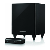
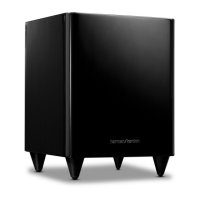
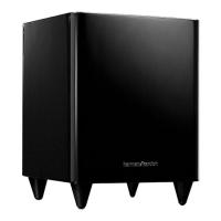
HKTS 200 SUB/230 + 210 SUB/230 Service Manual
 Loading...