BU80/HTS-10 rev. "A,B"
A. Power Amp Section
1. Resistance Check
Resistance from O/P of the module to GND should be >30K (NO LOAD)
Resistance from V+ of the module to V- of the module should read >5k
Resistance from V+ of the module to O/P of the module should read >30K
Resistance from V- of the module to O/P of the module should read >30K
2. Power Up LED RED
3. D.C. Operation
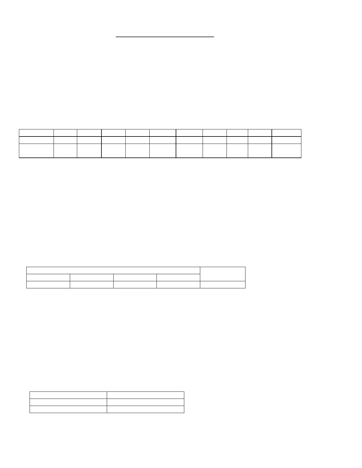
Voltage measurements (DVM)
Between +6V V+ O/P V- +15V S/D FR I/P GND -15V
And V- GND GND GND GND V- GND GND GND GND
Should be
Reading
+6.2V +38.7v 0V -38.7V +15.5V +5.75V 0V 0V 0V
-15.5V
4. Check Switching Frequency
Use scope (EITHER USES AN ISOLATION TRANSFORMER OR ATTACHES THE PROBE TIP TO SPK- and
REFERENCE LEAD TO SPK+)
-Reading 100kHz +/-10%,1Vpp
B. Pre Amp Section
1. Low Level Input Sensitivity
-Set up Turn level and Low-Pass Pot Fully CW
Generator set at 50mV@43Hz
Signal to Low level input
-Voltage measurements
OP AMP
U1(1) U1(14) U1(7) U1(8)
SPEAKER O/P
342mV 572mV 2.88V 2.63V 13.6V
2. High Level Input Sensitivity
-Set up Turn level and Lo Pass Pot Fully CW
Set Generator at 507mV@43Hz
Signal to High level input
Voltage measurements 13.6V at speaker output
3. Low-Pass
Set upSet Generator at 100mV@100Hz
Signal to Low level input
Measure voltage at speaker output
Voltage measurements
Low-Pass Pot Setting Output
CW 6.92V
CCW 3.53V
4. LED With a 35mV input signal at a single Low level input, LED should change to green
See flow chart (following page) for detailed diagnostics.
12
 Loading...