EasyManua.ls Logo

Harman JBL Club-4505 User Manual

Harman JBL Club-4505
21 pages
To Next Page IconTo Next Page
Page #1 background imageLoading...
Page #1 background image
Service Manual
Released by Global Quality SL
Ver. 1.0 07/2016
harman/kardon, Inc.
Club-4505
5 channel 1500watt full-range amplifier
CONTENTS
2
5
7
8
19
16
20
Safety Instruction, Warning & Notes
Specifications
Set Block Diagram
Schematic Diagrams
Layout Diagrams
Set Mechanical Exploded View
Packaging View
21
Spare Parts List
n
nel 1500watt
f
ull-ran
g
e ampli
f
ier
C
O
N
T
E
N
T
S
Question and Answer IconNeed help?

Do you have a question about the Harman JBL Club-4505 and is the answer not in the manual?

Harman JBL Club-4505 Specifications

General IconGeneral
BrandHarman
ModelJBL Club-4505
CategoryAmplifier
LanguageEnglish

Summary

Important Safety Instructions

FCC Regulations (USA Only)

Details FCC rules for RF energy transmission and reception.

IC Statement and Warning (Canada Only)

Provides Canadian compliance information for digital apparatus.

Antenna Grounding and Battery Safety

Guidelines for antenna grounding and safe battery handling/disposal.

ELECTROSTATICALLY SENSITIVE (ES) DEVICES

PRODUCT SAFETY NOTICE

Important safety precautions for servicing components and handling parts.

SAFETY PRECAUTIONS

LEAKAGE CURRENT CHECK

Procedure for measuring leakage current to ensure electrical safety.

JBL Club Amplifiers Overview

Authentic JBL Power and Performance

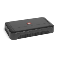
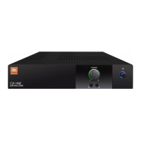
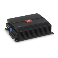
Highlights the performance and features of JBL Club amplifiers.

Key Features

Lists key features of the JBL Club amplifiers.

Compact Size and Input Options

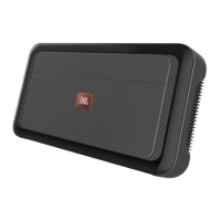
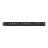
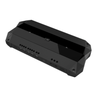
Describes compact design and high/low-level input integration.

Advanced Audio Controls

Details variable crossovers, bass boost, ADAS, and HALOsonic inputs.

What's in the Box and Specifications

Lists included items and provides detailed technical specifications.

Technical Diagrams

CLUB4505/REF4555a BLOCK DIAGRAM

Overall system block diagram illustrating signal flow and major components.

Schematics: Power and Control

Schematics for power supply, controller ICs, and protection circuits.

Schematics: Input and Pre-Amplifier Stages

Schematics for input signal processing, pre-amplifiers, and crossovers.

Schematics: Amplifier Output Stages

Detailed schematics for the output amplifier stages for all channels.

Schematics: Subwoofer Functions

Schematics for subwoofer input processing, crossover, bass boost, and limiter.

Schematics: ADAS and Halosonic Inputs

Schematics for ADAS and Halosonic input signal integration and processing.

Physical Layout and Assembly

Main Board Layout (Top View)

Top view layout of components on the main circuit board.

Pre-Amp Board Layout (Bottom View)

Bottom view layout of components on the pre-amplifier circuit board.

Pre-Amp Board Layout (Top View)

Top view layout of components on the pre-amplifier circuit board.

Mechanical Exploded View

Exploded view showing assembly order and component placement.

Packaging and Parts List

Packaging View

Diagram illustrating product packaging and included accessories.

Spare Part List

Comprehensive list of all replaceable parts with part numbers and descriptions.

Related product manuals