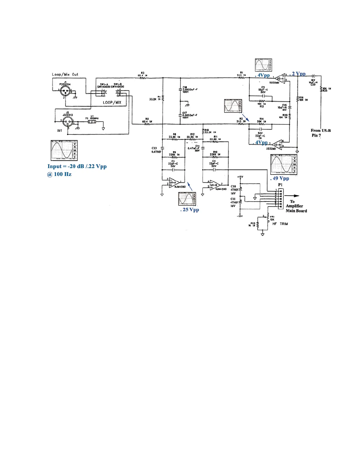
Loop/Mix Input Circuitry
The loop/mix circuitry, shown above, is another feature that makes the EON 10-G2 so
versatile. The user can decide which signal is output to extension male XLR jack J1. SW1
switches between the XLR input signal only or a mixture of the Tip Ring Sleeve and the
XLR input signals for increased sound reinforcement. In the “loop” or up position, the
incoming signal on XLR jack J2 is sent directly to the extension XLR jack J1. When the
switch is toggled, a mixture of the Tip Ring Sleeve and XLR line inputs are sent to the jack.
In either case, this allows the user to connect XLR cable to J1 and send audio signal to other
equipment.
Initially, the processed XLR input signal is summed with the TRS (Tip Ring Sleeve) ¼”
jack input signal at U5 via R31/R33 (not shown). Signal output from U5, located on pin 7,
passes through components C20, R35, R39, and enters the non-inverting inputs of U2A and
U2B. The bridge configuration of IC U2 allows for an increase in the voltage level while
providing a balanced output format. R3 and R5 in conjunction with C18 and C17 attenuate
electrostatic transients that could possibly be further amplified. The resultant signal
branches to SW1 where the looping option of connecting to the respective pins of XLR
output jack J1 for external amplification. Multiple feedback circuits of U1A and U1B
provide necessary isolation between the internal or main circuitry and externally connected
equipment. This configuration also prevents an increase in distortion and loading that could
be induced by external circuitry. Output of U1B is connected to pin1 of P1 for internal
amplification on the main PCB. C10 and C11 provide additional filtering of cable-induced
transients on the ±15 Vdc power supply lines.

 Loading...