Do you have a question about the Harman JBL EON10-G2 and is the answer not in the manual?
Balanced XLR input for microphones, consoles, and instruments.
1/4" jack for mono/stereo audio sources like players, keyboards, instruments.
XLR male output connector for sending audio to other equipment.
Controls input sensitivity (MIC/LINE) and output routing (MIX/LOOP).
Two-color LED indicating signal presence and clipping threshold.
LED indicates MIC/LINE switch position for Input 1.
Instructions for safely selecting mains voltage and fuse information.
Diagnosing issues related to excessive current draw, often due to shorted components.
Troubleshooting steps for absent or low internal voltages.
Diagnosing no sound issues related to control voltage absence.
Steps for no sound issues when voltages are confirmed correct.
Addressing issues causing reduced output power from the amplifier stages.
Troubleshooting steps for a non-illuminating power LED.
Steps to diagnose the absence of input signal indication on the unit.
Troubleshooting specific issues related to the microphone LED.
Initial checks and setup before powering on the unit.
Procedure to verify amplifier gain levels for LF and HF outputs.
Testing procedure for the secondary audio inputs.
Verifying output voltage levels for LF and HF under load.
Defines the original owner and subsequent owners covered by the warranty.
Details exclusions and inclusions of warranty coverage.
Clarifies responsibility for repair and shipping costs.
Procedures for seeking warranty service and repairs.
Legal limitations on implied warranties like merchantability.
Liability limitations for incidental or consequential damages.
Detailed acoustic and electrical performance data.
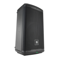
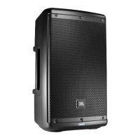
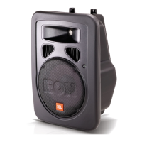
Lists key components of the EON10-G2 system.
| Frequency Range (-10 dB) | 45 Hz - 20 kHz |
|---|---|
| Max SPL | 121 dB |
| Woofer Size | 10 inches |
| Outputs | XLR |
| Horizontal Coverage | 90° |
| Vertical Coverage | 60° |
| LF Driver | 10 inches |
| Enclosure | Polypropylene |
| Type | Powered Speaker |
| Tweeter Size | 1 inch |
| Inputs | XLR, 1/4" |
| HF Driver | 1 inch |
| Input Connectors | XLR, 1/4" |