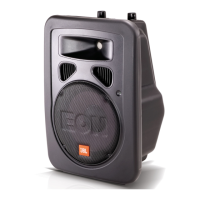
EON10-G2
Final Test Procedure
INITIAL POWER UP TEST
Setup—Serially connect a variac, isolation transformer and ammeter. Connect unit under test to
variac. Mic /Line switch should be Line position. Volume control at fully CCW position and no
load.
• Slowly increase the variac output voltage monitoring for excessive current usage
• Idle current should be less than .5 amps
• Power Green light ( FP ) should be illuminated
GAIN TEST
Setup---Monitor LF and HF output on oscilloscope with 8 Ohm load, volume CCW
• Apply –20 dB at 80 Hz sine wave from generator to the “ XLR” input 1.
• Increase volume control fully CW. LF Output signal should be 24 dB, ± 1 Db.
• Change sine wave frequency to 10 kHz. HF Output signal should be 14 dB, ± 1 dB.
INPUT 2 & 3
Setup---Monitor HF output on oscilloscope with 8 Ohm load, volume CCW
• Apply –20 dB at 10KHz sine wave from generator to the “ 1/4” Jack input 2
• Rotate the volume control (VR2&3) and verify smooth level change with no intermittent output.
• Repeat test for input 3
OUTPUT POWER TEST
Setup---Monitor LF Output
• Apply 80 HZ to input 1 and increase gain from generator until the peak LED begins to
illuminate.
• The output voltage, at this point, should be approximately 16 Volts (AC).
• Perform the same test for “HF” Output with 10Khz on input 1.
• The output voltage, should be approximately 6.5 Volts (AC).
 Loading...