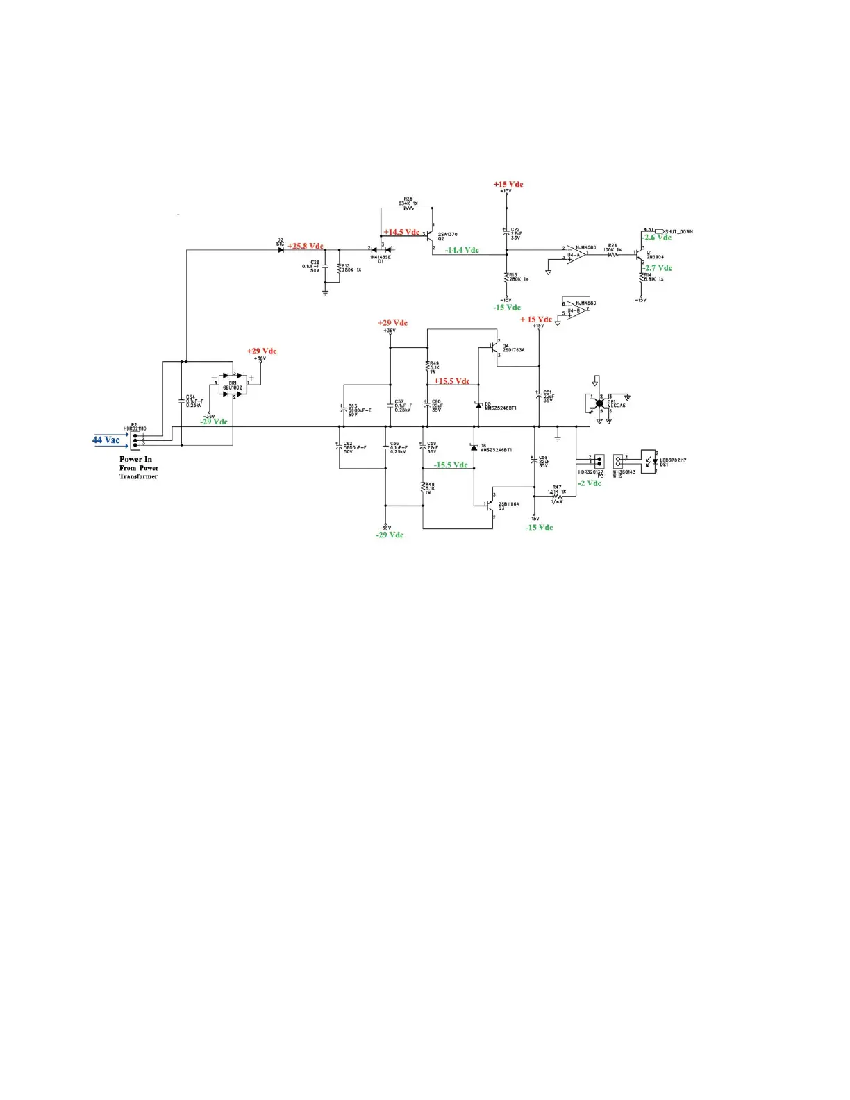
Power Supply
This is the power supply circuit of the EON 10-G2. Operational voltages, necessary of the
main amplifier and processing circuits, are created on this PCB. The schematic, shown
above, contains three individual circuits: the signal shutdown, the main rectification and low
voltage power supply circuits.
Note: Voltages documented minimally differed from published results and are
attributable to component tolerance variations.
Voltage rectification by BR1 modifies the 44Vac delivered by the toroidal power
transformer at P2 into the positive and negative 29 volts. This voltage feeds the main
amplifiers and the positive and negative 15 volt power supplies used for signal processing.
C63 and C62 filter this rectified voltage, respectively.
In the second circuit, Zener diodes D5 and D6 clamp the positive and negative 29 Vdc so
that voltage regulators Q3 and Q4 output positive and negative 15 Vdc. Further filtering of
this voltage occurs by C61 and C58. An LED, D51, is serially connected with R47 to
negative 15 Vdc and functions as the pilot lamp.
The third circuit, the signal shutdown circuit, monitors several different parameters: the
presence of ac voltage, the presence of the low voltage supplies and the output transistor
temperature. Absence of any voltage or excessive temperature detected will cause
comparator U4 to trigger Q1 resulting in muting of the audio output. The time constant of
C22/R15 provides the initial speaker delay time upon power up.

 Loading...