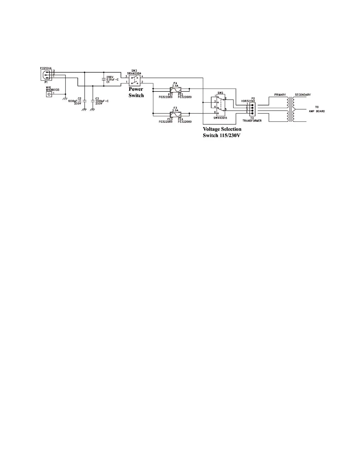
AC Input PCB
The line voltage of 117 Vac is connected at input jack P1 on the ac input PCB. Shunting
capacitor C1 reduces the probability of electronic damage that could occur should any
abnormalities exist on the input voltage. Capacitors C2 and C3 work in conjunction with
C1 to help stabilize this input voltage and reduce the instantaneous line voltage spikes that
could cause noise especially in the high frequency range. Pin 2, the neutral, is connected to
ground. Both lines of input voltage are directly connected to the 2-pole 2-position power
switch.
The operational idle current will be below the rated 2.5 amp fuses to protect the user from
fire. If the amplifier is consistently overdriven or an abnormality does exist with the
equipment, the fuses will open and current will cease to flow. After the fuses, the voltage
travels to the manually operated voltage selection switch. It is important to power down the
equipment when this switch is used to avoid possible driver damage. The switch,
essentially, determines which transformer primary is utilized. We will assume that the input
voltage is 115 Vac for this circuit description. The toroidal transformer output would then
deliver 44Vac to the power supply connector P2 on the main amplifier PCB.

 Loading...