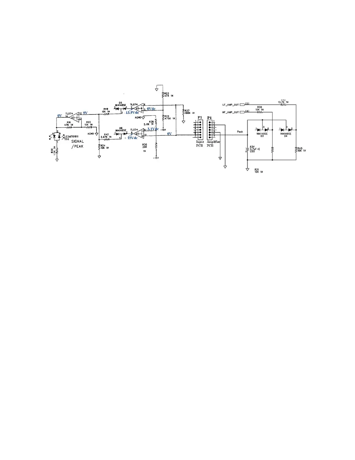
Peak/Signal Indicator
Signal indication is performed by the above circuitry with the possibility of three scenarios--
-normal ac signal present, no signal present and peak signal present.
Circuitwise, the high frequency and low frequency output taps are connected to D3 and D4
through R39 /R40 causing reverse charging of capacitor C55. This negative voltage is
transferred to the input PCB through interface connector P1 to window comparator U3. U3B
and U3C detect signal presence when the transferred voltage is greater than the lower
reference voltage of pin 5. Peak indication is detected when this transferred voltage is
greater than the upper reference voltage, at pin 9, which causes toggling of U3D to –15 volts
and illuminating the red portion of the LED, D52.
Voltage below the lower ref voltage causes no illumination.
Voltage above the upper ref voltage causes the red led to illuminate.
Voltage between the upper and lower ref voltages causes the green led to illuminate.
V
lower ref voltage =
0 volts
V
upper ref voltage
= -3.1 volts
 Loading...