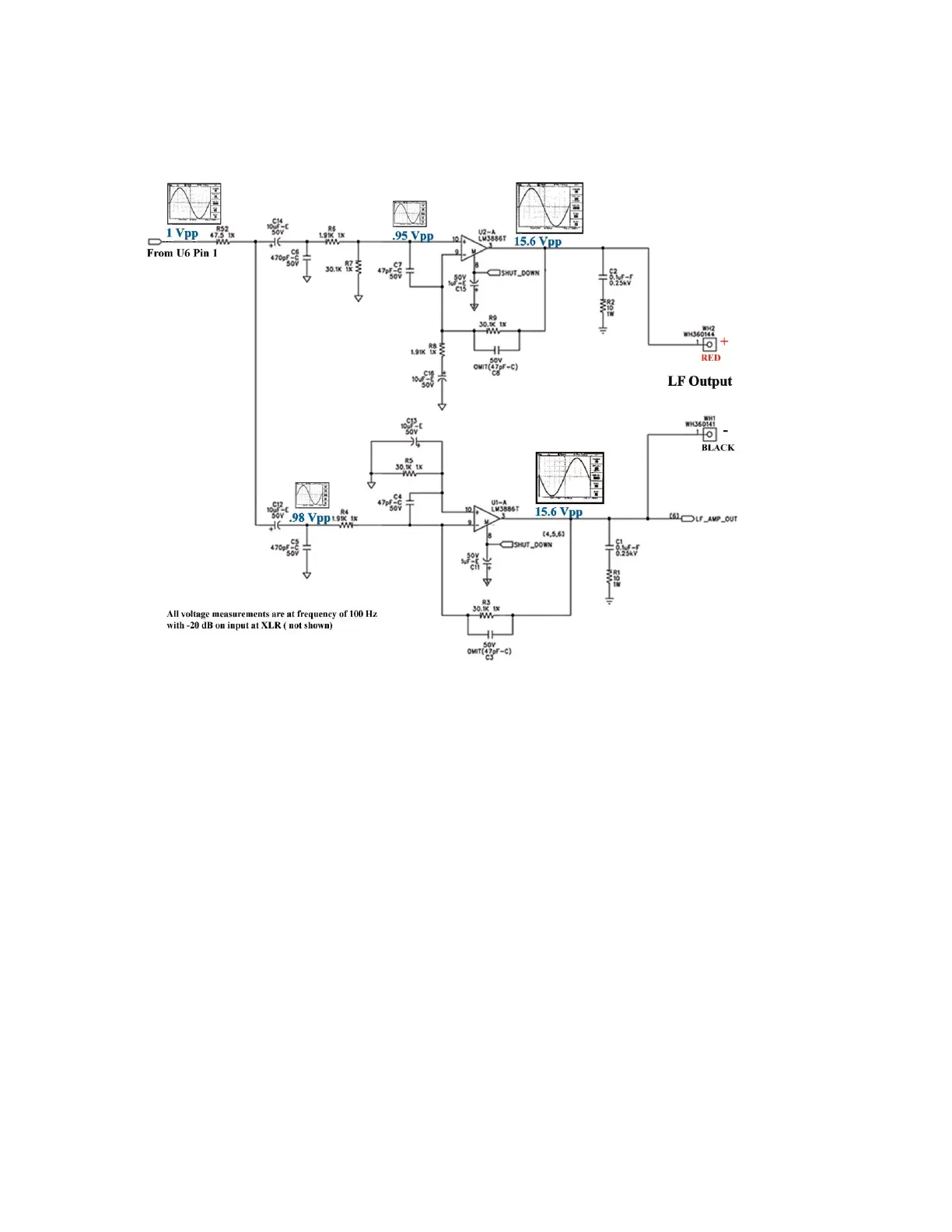
LF Amplifier Stage
This is the low frequency amplifier. The bridged mode configuration using two LM3886T
monolithic amplifiers, U1 and U2, enable twice the output voltage capability than if one IC
were driven alone. Therefore, it is strongly recommended this unit be connected to the
ac mains through an isolation transformer for safety purposes during the servicing of
the amplifier/ output stage. This will separate the grounds from interacting with the
test equipment, the unit under test and the technician.
A 1Vpp level output from U6 pin 1 from the low frequency processing circuits is input at
R52 and branches to each amplifier by passing through coupling capacitors C12 and C14.
Each leg carries this signal to the inverting and non-inverting inputs whereby IC’s U1 and
U2 increase the signal level to 15.6 volts.
Each audio output IC at pin 8 is connected to the detection circuit driver, Q1 (not shown
here—but located in the power supply section) for temperature, voltage and current
abnormalities. Before replacing both the output IC’s to correct a unit with a ‘no sound’
problem, check to verify that this muting line is not detecting a fault elsewhere (--for normal
operation it should be a negative low).
 Loading...