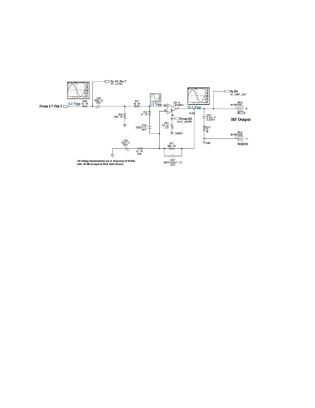
HF Amplifier Stage
After the increase in signal level from U7 pin 1 to 1.1Vpp, the signal enters the monolithic
power amplifier IC, U3, at pin 10 via R18, C20 and R11. R12/C23 at the inputs avoid the
possibility of phase distortion in the rated 50 Watt output and effectively makes use of
common mode rejection to eliminate any induced noise within the audio range. This also
prevents any ultra-high frequency oscillation that could cause premature IC failure. C21
adds stability to the mute line and avoids any erroneous triggering from Q1. Connecting P1
pin 7 at junction R18/C20 activates the user adjustable trim potentiometer, VR1 on the input
PCB, for a more custom sound. Also, the output of U3 pin 3 is connected to P1 pin 6 and
transferred to the peak/signal detection and indicator circuitry on the input/output PCB.
 Loading...