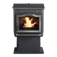
20P 6 1 A P ellet S tove
3 -9 0 -0 5 8 2 2 R 2 8 _ 0 8 /1 3
Low Draft V oltage Adj ustment
These units are pre-tested at the factory with exactly 120 AC,
0 Hz. They are checked and adusted for rebox tightness,
gasket leakage, motor operation and igniter operation. The
P1A is then factory set at a mid-point adustment and in most
cases will not need any adustments. NOTE: The factory low
draft setting may not be correct for the unit' s permanent
installation conditions.
The control board on the P1A is equipped with a low draft
adustment port. Located on the control face ust to the right
of the igniter light. This voltage adustment is provided to allow
the unit to be adusted for the household voltage where the
unit is going to be in permanent operation. NOTE: The line
voltage varies from area to area and often home to home.
The low draft voltage should be adusted to achieve the most
efcient burn on low burn or maintenance. This voltage
adustment allows the installer to change the low voltage
set point approximately 10 volts. This adustment should
be done by the installer during set up because a draft meter
reading is req uired to insure proper set up.
If the unit is not adusted properly, it does not cause a safety
concern. If the unit is adusted too high, only efciency is lost.
If the unit is adusted too low, the low draft pressure switch
will not allow the feed motor or the igniter to operate.
Combustion Motor
Speed Control
Low draft only set
point.
The small straight
screwdriver slot is
plastic; therefore, the
unit can be adjusted
while in operation.
F ig.2 2
F ig. 2 3
Draft Meter bolt hole
location
The draft test hole is under
the left rear corner of the
rebox.
Low Draft V oltage Adj ustment
A simple draft test should be performed after completing the
ue pipe installation. To record the results for future reference:
1. Plug unit into a 120 AC, 0 Hz outlet.
2. Close the hopper lid, front view door, and the ash pan.
Neither pellets or a re are required for this test.
. With the mode selector in the O position, turn the feed
aduster to TEST.
. Record the high draftin W.C. (Normal is -.50 to -.0)
The control will be on the High raft for a total of 1 minute.
5. After the minute, the combustion motor will go down to
low draft and the distribution blower will go on high. Allow
approximately 15 seconds to pass for the combustion
motor to slow before checking the low draft.
. If the low draft is between -.5 and -.5, record the reading
in W.C. If the reading is higher, slowly turn the
set screw counter-clockwise until the draft lowers. If the
reading is lower, very slowly turn the set screw clockwise
until the draft increases.
NOTE: In some cases, the draft may not go as low as
-.3 5 to -.4 5 even with the set screw completely counter-
clockwise. Ideally, you should j ust set it as low as
possible.