HLP
4200 Instruction Manual
Harmonic
Lightwaves
In some cases the RJ11 connectors
on
the cables are
aligned differently. When this happens,
“OUT”
and
“IN” must be exchanged
so
that
“OUT”
connects to
‘‘OUT’’
and “IN’ connects to “IN’.
The most effective way to daisy chain systems properly
is to connect them one by one. If
a
system does not
communicate, and it is verified that the address and
connections are correct, try to connect the incoming
cable to the
“OUT”
connector. If this
works,
connect
the next unit from the “IN’ connector and test it the
same way.
2.4.3 External
Alarm
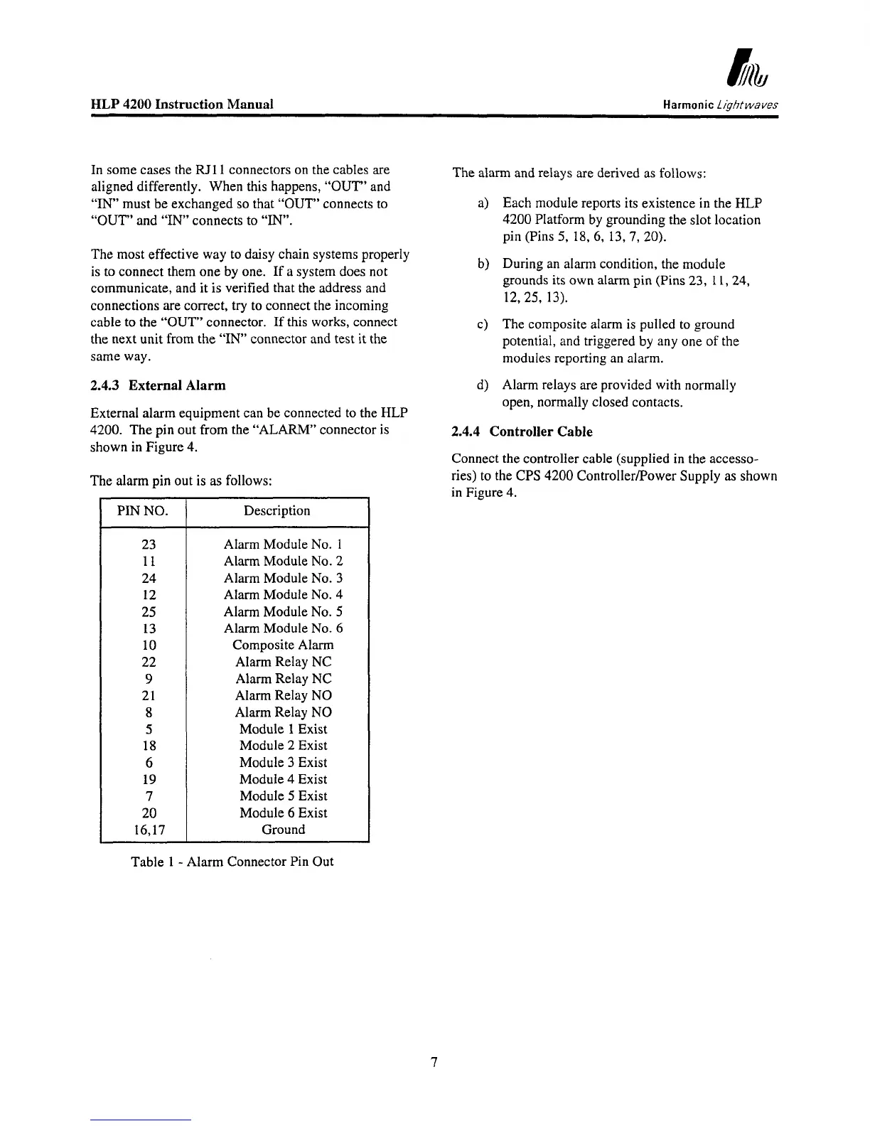
External alarm equipment can be connected to the HLP
4200. The pin out from the “ALARM” connector
is
shown
in
Figure 4.
The
alarm
pin out is
as
follows:
PIN NO.
23
11
24
12
25
13
10
22
9
21
8
5
18
6
19
7
20
16,17
Description
Alarm Module
No.
1
Alarm Module No. 2
Alarm Module No. 3
Alarm Module
No.
4
Alarm Module No.
5
Alarm Module
No.
6
Composite Alarm
Alarm Relay NC
Alarm Relay NC
Alarm Relay NO
Alarm Relay NO
Module
1
Exist
Module 2 Exist
Module 3 Exist
Module 4 Exist
Module
5
Exist
Module
6
Exist
Ground
The
alarm
and relays are derived
as
follows:
a)
Each module reports its existence
in
the
HLP
4200 Platform by grounding the slot location
pin (Pins
5,
18,
6, 13,
7,
20).
b)
During an
alarm
condition, the module
grounds its own alarm pin (Pins
23,
11,24,
12,25,
13).
c) The composite alarm is pulled to ground
potential, and triggered by any one
of the
modules reporting an alarm.
d) Alarm relays are provided with normally
open, normally closed contacts.
2.4.4 Controller Cable
Connect the controller cable (supplied
in
the accesso-
ries) to the
CPS
4200 ControllerPower Supply
as
shown
in
Figure 4.
Table
1
-
Alarm Connector Pin Out
7