Do you have a question about the Harmony One and is the answer not in the manual?
Essential safety measures for static discharge and part identification before starting the installation.
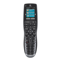
Visual identification of all components involved in the Harmony One front cover replacement process.
Locating and removing screws from the battery compartment to begin disassembly.
Detaching the outer rubberized back plate using a pry tool.
Removing three internal screws after the back plate is off to expose more components.
Carefully prying apart the front and back halves of the remote casing.
Removing screws holding the logic board and disconnecting the touch screen ribbon cable.
Gently lifting and rolling the logic board from the front cover to avoid ribbon cable damage.
Placing button pads and the plastic guide onto the new front cover correctly.
Aligning the logic board with the front cover and mounting posts.
Carefully re-inserting the touch screen ribbon cable and securing its clamp.
Replacing logic board screws and testing button alignment and tactile response.
Aligning and pressing the back cover plate onto the logic board assembly.
Pressing the front and back pieces together to snap the locking tabs into place.
Replacing screws to attach the back cover and snapping the rubberized outer piece.
Reinstalling the final four screws in the battery compartment and re-applying the sticker.
| Device Type | Universal Remote Control |
|---|---|
| Brand | Logitech |
| Model | Harmony One |
| Display | Color touchscreen |
| Battery Type | Rechargeable Lithium-ion |
| Number of Devices Supported | Up to 15 devices |
| Activity-Based Control | Yes |
| Learning Capability | Yes |
| Charging Cradle | Yes |
| PC Programmable | Yes |
| Programmable Buttons | Yes |
| Range | Up to 30 feet |
| Connectivity | Infrared |
| Compatibility | Supports 225, 000+ devices from 5, 000+ brands |