Quick Guide
14221-1100-1010
Sep/11
XG-75 Portable Radios
EDACS
®
, Conventional, P25
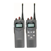
XG-75 Radio Controls
Top View Side View
Power On-
Off/Volume
Control Knob
Rotate clockwise to apply power to the radio
and increase the volume.
Rotate counter-clockwise to decrease volume
and power off radio.
System/Group/
Channel Control
Knob
A 16 position rotary knob for selecting systems
or groups/channels (set during programming).
Emergency/
Home Button
Pre-programmed to declare an emergency or
select a pre-set Home group/system. One or
the other can be assigned to this button.
PTT Button The PTT button is pressed to transmit.
Option Button
Pre-programmed to activate one software
option.
Clear/Monitor
Button
(Option Button 2)
Trunked mode: Used to exit the current
operation and terminate special calls.
Conventional mode: Used to monitor channels
and temporarily remove Channel Guard
decoding from a channel.
A/B Switch
Pre-programmed to choose between 2 software
options.
XG-75 Radio Keypad Functions
Locking/Unlocking Keypad
1. Press the
button.
2. Within 1 second, press the Option button
on the side
of the radio.
Selects systems, groups, or channels.
Secondary Function
: Changes the selection for an
item within a list.
Accesses the pre-stored menu.
Secondary Function
: Activates a selected item within a
list. (Similar to an “Enter” key.)
(Scan Model) Adds/Deletes selected groups or
channels from SCAN list of the currently selected
system.
(Scan Model) Toggles SCAN operation ON and OFF.
(Scan Model) Activates one of any programmable
software options selected during the PC programming,
including: high/low TX power and talkaround.
XG-75 Radio Keypad Functions (cont’d)
(System Model) Selects a specific system.
(System Model) Selects a specific group.
(System Model) Toggles SCAN operation on and off.
(System Model) Enables Private mode for the
system/group/channel displayed.
(System Model) Adds groups or channels from the
currently selected system to the SCAN list.
(System Model) Accesses the status list (0-9). The
Status key permits the transmission of a pre-
programmed status message to an EDACS or P25
site.
(System Model) Accesses the message list (0-9).
The Message key permits the transmission of a pre-
programmed message to an EDACS or P25 site.
(System Model) Deletes a selected group or channel
from the SCAN list of the currently selected system.
(System Model) Initiates telephone interconnect
calls.
(System Model) Initiates individual (unit-to-unit)
calls.
1 – 9
* 0 #
(System Model) Keys used to place telephone
interconnect and individual (unit-to-unit) calls.
Functions as a telephone keypad.
XG-75 Alert Tones
(T) = trunked only (B) = both trunked and conv modes
Ready-to-
Talk (B)
One short mid-pitched tone. OK to talk after
pressing PTT button.
Call
Queued (T)
One high-pitched tone. Call queued for processing.
Autokey (T)
One mid-pitched tone. Queued call received
channel assignment.
System
Busy (T)
Three low-pitched tones. System busy or unable to
complete the call.
Call
Denied (T)
One low-pitched tone. Radio not authorized on the
system or group.
Carrier
Control Timer
(B)
Five high-pitched tones and one long low-pitched
tone. PTT pressed for too long.
Low
Battery (B)
One low-pitched and one short mid-pitched tone.
Low battery. Replace battery immediately.
TX Low
Battery
Alert (B)
Transmit Lockout: One low-pitched tone after PTT.
Battery too low to transmit.
Attach Battery Pack
1. Align the tabs at each side on the bottom of
the battery pack with the slots at the bottom
of the battery cavity.
2. Push the top of the battery pack down until
the latches click to attach the battery to the
radio.
3. Tug gently to verify that the latches are
secure and the battery pack is properly
attached to the radio.
Remove Battery Pack
1. Pull both latches on either side of the battery
pack toward the bottom of the radio
simultaneously.
2. Pull the battery away from the radio.
3. Remove the battery pack from the radio.
Quick Guide
14221-1100-1010
Sep/11
XG-75 Portable Radios
EDACS
®
, Conventional, P25
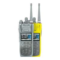
XG-75 Radio Controls
Top View Side View
Power On-
Off/Volume
Control Knob
Rotate clockwise to apply power to the radio
and increase the volume.
Rotate counter-clockwise to decrease volume
and power off radio.
System/Group/
Channel Control
Knob
A 16 position rotary knob for selecting systems
or groups/channels (set during programming).
Emergency/
Home Button
Pre-programmed to declare an emergency or
select a pre-set Home group/system. One or
the other can be assigned to this button.
PTT Button The PTT button is pressed to transmit.
Option Button
Pre-programmed to activate one software
option.
Clear/Monitor
Button
(Option Button 2)
Trunked mode: Used to exit the current
operation and terminate special calls.
Conventional mode: Used to monitor channels
and temporarily remove Channel Guard
decoding from a channel.
A/B Switch
Pre-programmed to choose between 2 software
options.
XG-75 Radio Keypad Functions
Locking/Unlocking Keypad
1. Press the
button.
2. Within 1 second, press the Option button
on the side
of the radio.
Selects systems, groups, or channels.
Secondary Function
: Changes the selection for an
item within a list.
Accesses the pre-stored menu.
Secondary Function
: Activates a selected item within a
list. (Similar to an “Enter” key.)
(Scan Model) Adds/Deletes selected groups or
channels from SCAN list of the currently selected
system.
(Scan Model) Toggles SCAN operation ON and OFF.
(Scan Model) Activates one of any programmable
software options selected during the PC programming,
including: high/low TX power and talkaround.
XG-75 Radio Keypad Functions (cont’d)
(System Model) Selects a specific system.
(System Model) Selects a specific group.
(System Model) Toggles SCAN operation on and off.
(System Model) Enables Private mode for the
system/group/channel displayed.
(System Model) Adds groups or channels from the
currently selected system to the SCAN list.
(System Model) Accesses the status list (0-9). The
Status key permits the transmission of a pre-
programmed status message to an EDACS or P25
site.
(System Model) Accesses the message list (0-9).
The Message key permits the transmission of a pre-
programmed message to an EDACS or P25 site.
(System Model) Deletes a selected group or channel
from the SCAN list of the currently selected system.
(System Model) Initiates telephone interconnect
calls.
(System Model) Initiates individual (unit-to-unit)
calls.
1 – 9
* 0 #
(System Model) Keys used to place telephone
interconnect and individual (unit-to-unit) calls.
Functions as a telephone keypad.
XG-75 Alert Tones
(T) = trunked only (B) = both trunked and conv modes
Ready-to-
Talk (B)
One short mid-pitched tone. OK to talk after
pressing PTT button.
Call
Queued (T)
One high-pitched tone. Call queued for processing.
Autokey (T)
One mid-pitched tone. Queued call received
channel assignment.
System
Busy (T)
Three low-pitched tones. System busy or unable to
complete the call.
Call
Denied (T)
One low-pitched tone. Radio not authorized on the
system or group.
Carrier
Control Timer
(B)
Five high-pitched tones and one long low-pitched
tone. PTT pressed for too long.
Low
Battery (B)
One low-pitched and one short mid-pitched tone.
Low battery. Replace battery immediately.
TX Low
Battery
Alert (B)
Transmit Lockout: One low-pitched tone after PTT.
Battery too low to transmit.
Attach Battery Pack
1. Align the tabs at each side on the bottom of
the battery pack with the slots at the bottom
of the battery cavity.
2. Push the top of the battery pack down until
the latches click to attach the battery to the
radio.
3. Tug gently to verify that the latches are
secure and the battery pack is properly
attached to the radio.
Remove Battery Pack
1. Pull both latches on either side of the battery
pack toward the bottom of the radio
simultaneously.
2. Pull the battery away from the radio.
3. Remove the battery pack from the radio.
Copyright© 2011 Harris Corporation.
Copyright© 2011 Harris Corporation.