GU320a Controller Manual
12
2.1
V Low Alarm 0V AC45~20000V 0 (no setting)
2.2
V Low preALM 198V AC45~20000V 0 (no setting)
2.3
V High preALM 253V AC45~20000V 29999 (no setting)
2.4
V High Alarm
29999
AC45~20000V 29999 (no setting)
2.5
I High preALM 9999A 0~9999A 9999 (no setting)
2.6
I High Alarm 9999A 0~9999A 9999 (no setting)
2.7
Alarm delay 10s 0~600s
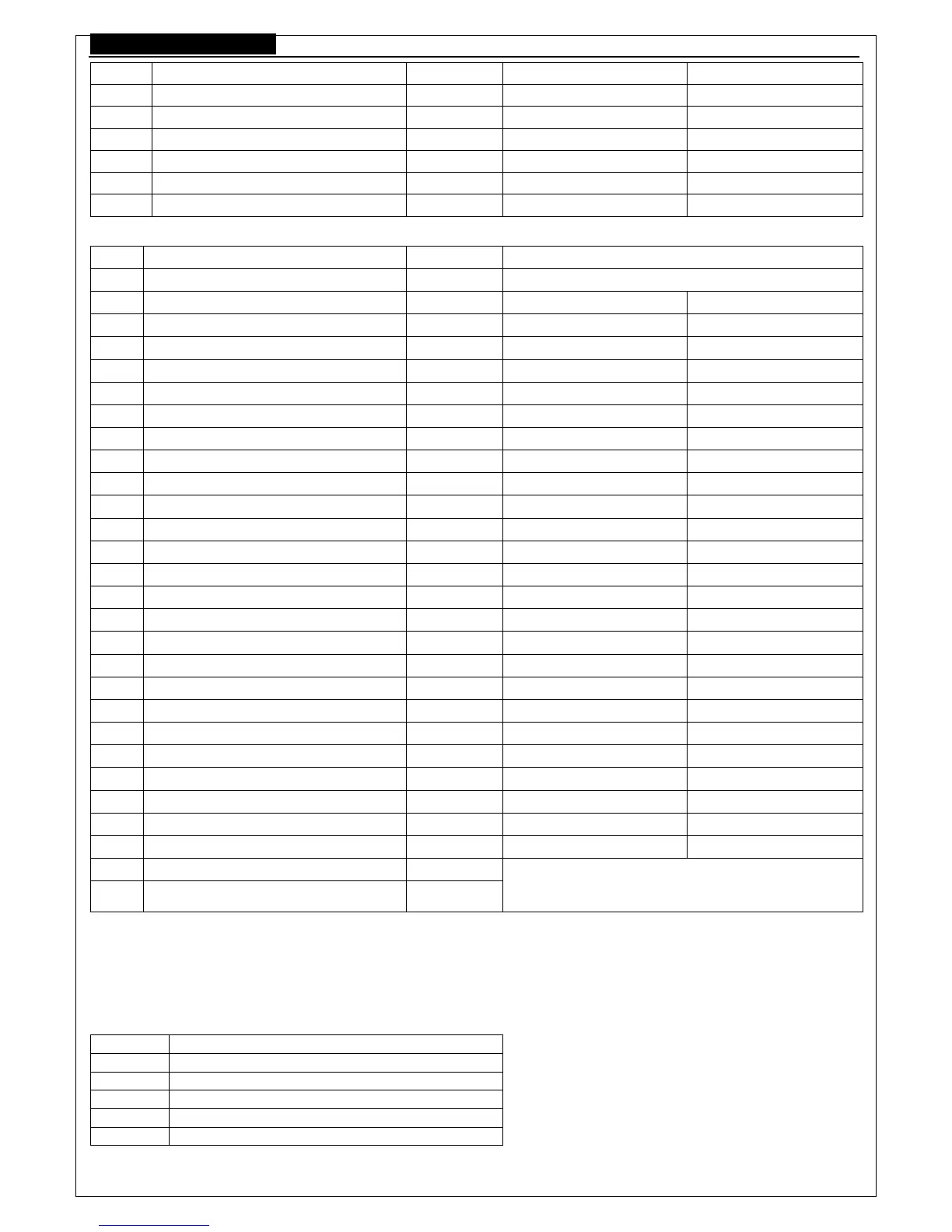
8.3 ENGINE
NO. Item Preset Range
3.0
QUIT
3.1
Nominal speed 1500 99-9999 RPM
3.2
Pickup frequency 3000 1-9999 Hz
3.3
Set pickup now
3.4
Fuel mode 0 0~1 0(NC) 1 (NO)
3.5
T-sensor mode 0 0~8 0 (no use)
3.6
P-sensor mode 0 0~9 0 (no use)
3.7
H-sensor mode 0 0~1 0 (no use) 1 (use)
3.8
Start delay 10s 0~300 s
3.9
Crank attempt 3 1~10s
3.10
Crank time 8s 0~30 s
3.11
Crank reset 15s 0~300 s
3.12
Crank disconnect 300RPM 1-9999 RPM
3.13
Idle delay
0 秒
0~9999s
3.14
Safety-on delay 60s 0~600s
3.15
Cooling delay 300s 0~600 s
3.16
Stop delay 20s 0~60s
3.17
Under SP Alarm 0 RPM 0-9999 RPM 0 (no setting)
3.18
Under SP preALM 1440 RPM 0-9999 RPM 0 (no setting)
3.19
Over SP preALM 1600 RPM 0-9999 RPM 9999 (no setting)
3.20
Over SP Alarm 1710 RPM 0-9999 RPM 9999 (no setting)
3.21
Oil-P low Alarm 140KPa 50~300Kpa 0 (no setting)
3.22
Oil-P low preALM 220KPa 50~300Kpa 0 (no setting)
3.23
Coolant preALM
95℃ 70~160℃
9999 (no setting)
3.24
Coolant Alarm
105℃ 70~160℃
9999 (no setting)
3.25
Batt low preALM 8.0V 1~25V 0 (no setting)
3.26
External. Alarm 0
3.27
External analog 2
0 unit V, 1 unit %, measuring 0-5v signal.
2 unit %, self determine the input according to the
resistance type and sensor data.
8.4 Note for pressure and temperature sensor
Different type of P-sensor and T-sensor according to the table followed, if the sensor available is not in the table, then
write the sensor parameter into the controller through the software, and the sensor setting in the parameter setting should be
the last type “user define”
Pressure sensor
NO. Type
0
NOT USE
1
VDO 10 bar
2
VDO 5 bar
3
Datcon 10 bar
4
Datcon 7 bar
 Loading...