5
Connecting to the HART Device
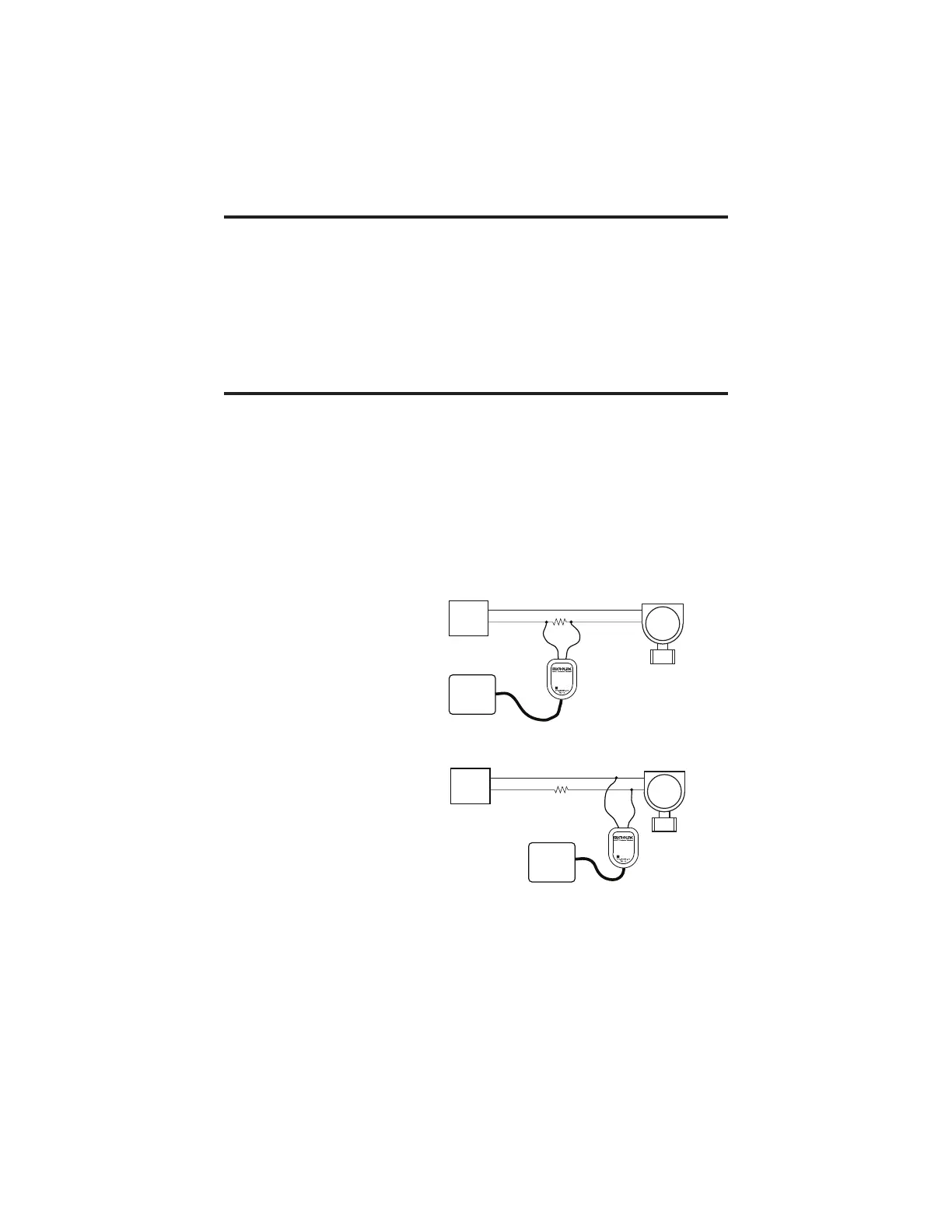
Connect the two mini-clips to the HART device or HART loop. MicroLink
provides electrical isola on between the HART loop and the PC. It is safe to
ignore grounding and polarity issues when making the HART connec ons.
The HART protocol requires a loop resistance of 230 to 600 ohms, typically
250 ohms. Refer to your equipment installa on instruc ons for details on
connec ng a HART protocol modem or confi gura on device to the loop.
Software Setup
Make sure your HART so ware is set to use the same serial COM port number
that the MicroLink modem is assigned to.
There are no hardware se ngs required by the MicroLink modem and modem
power is provided by the USB port. All other se ngs, such as BAUD rate and
parity, are taken care of by your HART so ware.
LOOP
POWER
SUPPLY
HART
DEVICE
250Ω
COMPUTER
Microflex
LOOP
POWER
SUPPLY
HART
DEVICE
250Ω
COMPUTER
Microflex
MicroLink HART modem connected
across the HART loop resistor.
MicroLink HART modem connected
across the HART device.
Two common methods for connecting the HART modem to a loop powered device.