Han
®
GigaBit
7
Ⓒ
Han
®
S
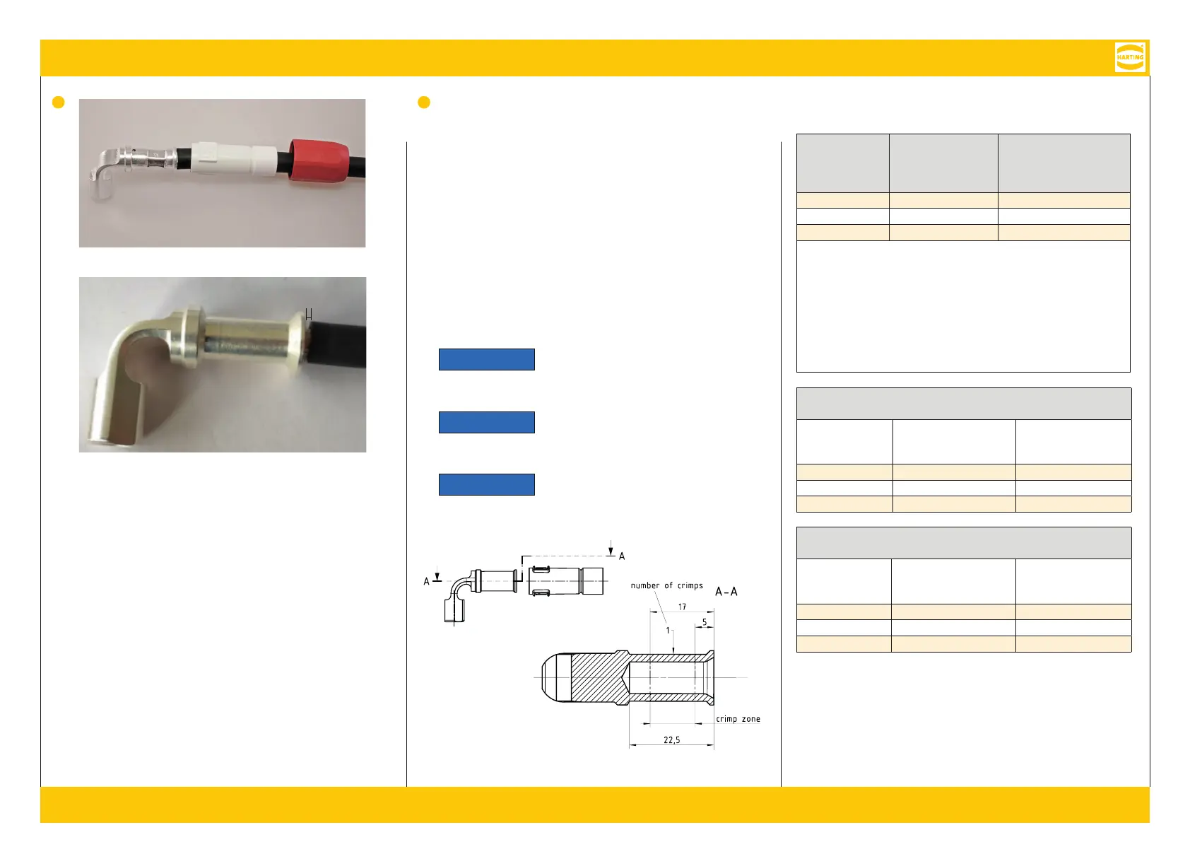
Crimp information / C-I /
Données de sertissage
Female contact /
B /
Contact femelle
Crimp die /
C /
Matrice de sertissage
Cable outer diameter /
K/ Diamètre exté-
rieur du câble
25 mm² 10 8.9 - 10.3 mm
35 mm² 12 11.4 - 12.2 mm
50 mm² 14 13.2 - 15.3 mm
Crimp zone acc. to DIN EN 46235; crimp die identification for stranded
fine wires acc. to VDE 0295 class 5 / IEC 60228 class 5; stripping
length: 22 mm.
C DIN EN 46235; C
L VDE 0295 K / IEC 60228 K 5; A-
: 22 mm.
Zone de sertissage selon DIN EN 46235 ; identification de la matrice de
sertissage pour fils toronnés fins selon VDE 0295 classe 5 / IEC 60228
classe 5 ; longueur de dénudage : 22 mm.
Crimping tool / C / Outil de sertissage
09 99 000 0850 & 09 99 000 0851
Female contact /
B /
Contact femelle
Crimp die /
C /
Matrice de sertissage
Part no. /
A./
Référence
25 mm² 10 09 99 000 0854
35 mm² 12 09 99 000 0855
50 mm² 14 09 99 000 0856
Crimping tool / C / Outil de sertissage
09 99 000 0860 & 09 99 000 0861
Female contact /
B /
Contact femelle
Crimp die /
C/
Matrice de sertissage
Part no. /
A./
Référence
25 mm² 10 09 99 000 0864
35 mm² 12 09 99 000 0865
50 mm² 14 09 99 000 0866
Ⓒ
First, slide the cable gland ③ and then the rubber sleeve ⑤ over
the cable before crimping the female contact ④. Insert the wire
strands completely into the crimp ferrule and start the crimping
process using the appropriate tools. No gap wider than 2 mm must
remain between the female contact ④ and the outer jacket.
S S K③
G⑤ K, B ④
. F S L
C S C
W. Z B ④
A S > 2 .
Tout d’abord poussez le presse-étoupe ③ et puis le manchon en
caoutchouc ⑤ sur le câble pour sértir le contact femelle ④ . Insérez
les fils dénudés complètement dans l’embout à sertir et commencez le
sertissage avec un outil approprié. Aucun espace supérieur à 2 mm ne
doit subsister entre le contact femelle ④ et la gaine extérieure.
Notice
Crimping must be done in a concen-
tric movement. Inclination can lead
to assembly problems.
Hinweis
D C
. S
M .
Avis
Le sertissage doit être fait dans un
manière centrique. L’inclinaison peut
causer des problèmes de montage.
max. 2 mm
 Loading...