8
The electric power card must be changed, if
• indicator light 8 shows the heater is on, but
it is not starting to heat up (contactors/relays
are not connected)
• contactors/relays are in the on position but
the heater does not come on
Blown fuses (fig. 10)
• if the indicator lights on the display card and
numbers do not glow, it may be that the main
fuse (32 mA) in the electric power card has
blown.
• if, though, the sauna light connected via the
control unit does not come on, it may be that
the light fuse has blown.
Faults in the thermostat’s sensor circuit
The codes Er1, Er2 and Er3 show up on the numerical
display if there is a break or faulty connection in
the thermostat’s sensor circuit (see instructions
for assembly and use). The resistance of the NTC
thermistor is 22 kΩ (kilo ohm) at +25
o
C.
If the overheating limiter of the thermostat trips,
it can easily be reset as soon as the fault has been
located and eliminated. Figure 16.
Die Leistungsplatte muß gewechselt werden, wenn
• die Kontrolleuchte (8) anzeigt, daß der Ofen
eingeschaltet ist, der Ofen sich aber nicht
erwärmt (Kontaktgeber/Relais schalten sich
nicht ein)
• die Kontaktgeber/Relais angezogen sind, sich
der Ofen aber nicht einschaltet
Sicherungsdefekt (Abb. 10)
• Wenn die Kontrolleuchten und Nummern der
Anzeigeplatte nicht leuchten, kann die
Hauptsicherung (32 mA) der Leistungsplatte
defekt sein.
• Wenn das über das Steuergerät angeschlossene
Licht in der Sauna nicht brennt, kann die
Sicherung des Lichts defekt sein.
Defekte im Fühlerkreis des Termostats
Die numerische Anzeige gibt Er1, Er2 oder Er3 an, wenn
im Fühlerkreis des Termostats eine Unterbrechung oder
ein Schaltfehler auftritt (siehe Installations- und Bedien-
ungsanleitung). Der Widerstand des Heißleiters
beträgt 22 kΩ (kilo ohm) bei einer Temperatur von
+25
o
C.
Wenn der Überhitzungsschutz ausgelöst wird,
kann er leicht zurückgestellt werden, nachdem
der Fehler zunächst gefunden und dann behoben
worden ist. Abb. 16.
EN
DE
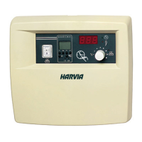
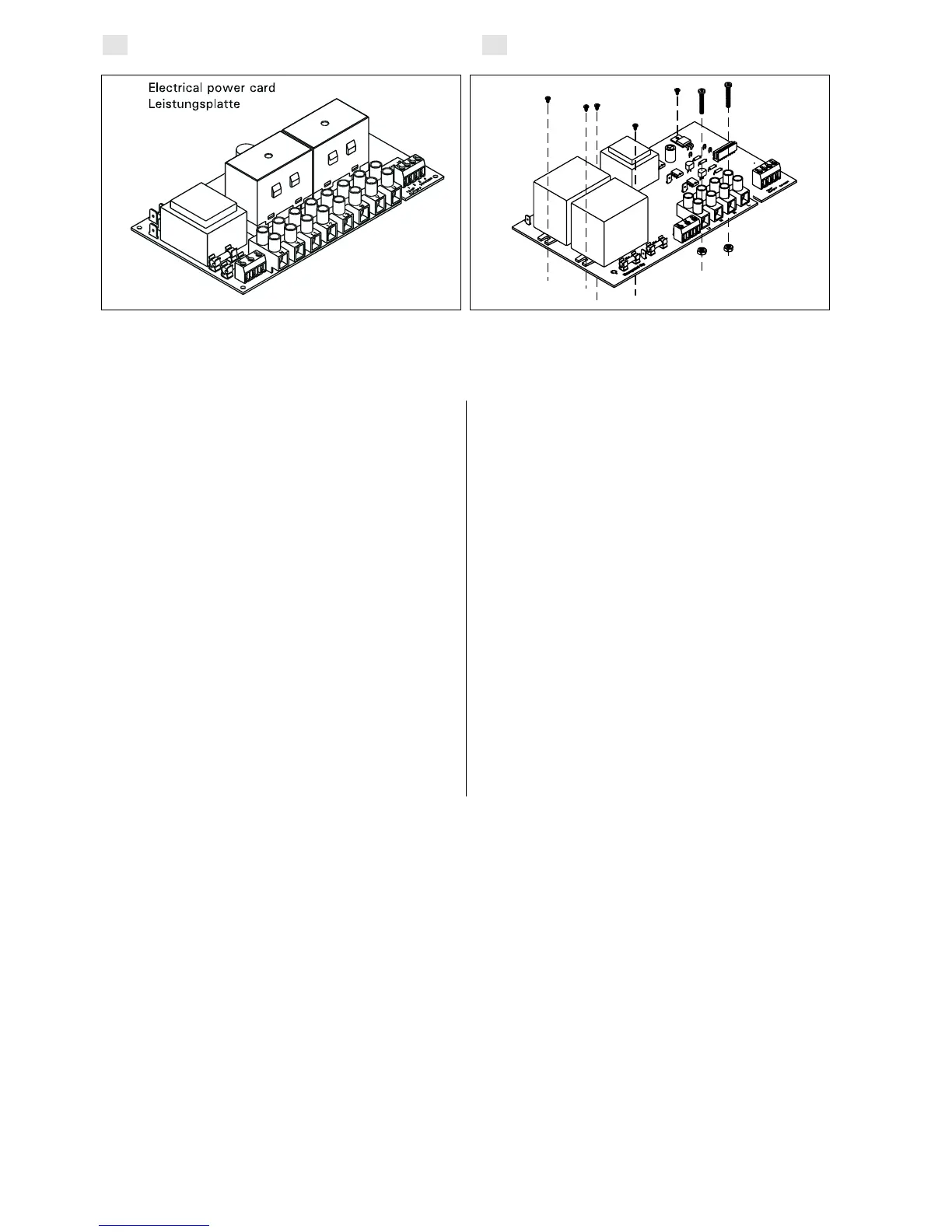
Figure 9a. Electrical power card C150
Abbildung 9a. Leistungsplatte C150
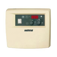
Figure 9b. Electrical power card C80
Abbildung 9b. Leistungsplatte C80