XB-P / XB-A 8
PART
NAME
111
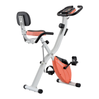
Cushion
Adjusng
Knob
PART
DIAGRAM
NO. QT Y.
11
10
17
Attach seat (10) into Main Frame (17), use Adjustable Knob for Seat (11) to x. The height can
be adjusted after assembly.
Step 5
PART
NAME
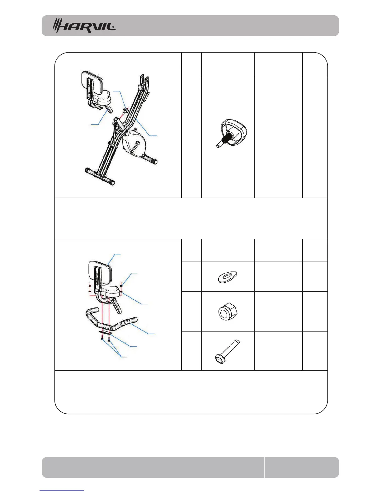
Arc Washer
(M8)
2
2
8
Lock Nut
(M8)
27
3
Semi-Round
Head Screw
(M8 x 35)
PART
DIAGRAM
NO. QT Y.
To align hole site of Back Armrest (4) & Back (5), Use M8*40 Semi-Round Head Screw (3), Back
Stator (2), Ø8.5 Arc Washer (8), M8 Lock Nut (7) to connect and tighten M8 Lock Nut (7).
Step 6
ASSEMBLY INSTRUCTIONS
5
8
3
7
4
2