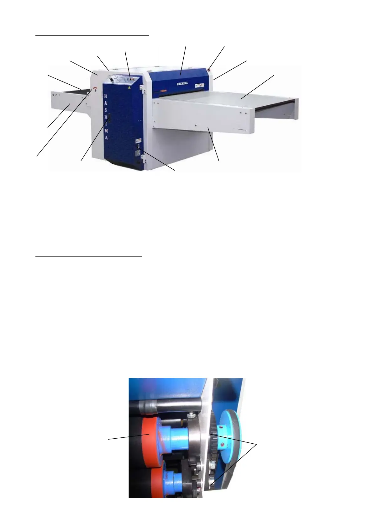
2.Outer component parts name
1. OPERATION PANEL 2. UPPER COVER
3. FRONT COVER 4. REAR COVER
5. RIGHT COVER 6. LEFT COVER
7. STRAIGHT CONVEYOR 8. WORK TABLE
9. WORK TABLE FRAME 10.STRAIGHT CONVEYOR FRAME
11. WIRING BOX KNOB 12. CIRCUIT BREAKER
13.EMERGENCY SWITCH 14.EMERGENCY HANDLE POSITION
3. INSTALLATION INSTRUCTION
※ Don’t fail to entrust the electric construction work shop with the power source before
you’ll install the power source for exclusive use. And don’t fail to ground with sure,
and then confirm whether there exists the electric leak breaker or not, before you’ll
entrust with it without fail, if necessary.
※ Install the machine with the weight of 450kg to the solid location on the floor .
1. Decide the installation place of the machine.
2. Put the fixing plates (provided) under the adjusting bolts properly.
3. Install the work table. (Straight rite, Return rite only)
4. Level the machine precisely with a level, adjusting the adjusting bolts. Put the level
on the work table for front side leveling, and put the level on the power pressure roller
for rear side leveling.
5. Don’t fail to take the plastic film off cleaner of the Teflon belt, which is covered
with the plastic film before you connect the power source.
6. Put the HASHIMA grease in four sites of the bearing of the pressure roller.
圧力ローラー
压
力胶辊
PRESSURE
注油
加油
REFUE
L
⑭
①
②
④
⑤
③
⑥
⑨
⑧ ⑦
⑩
⑪
⑫
⑬
From the Library of Superior Sewing Machine & Supply LLC