English
Form No. GRSM-0719
21
OPTIONS AND ACCESSORIES
Changing the Setpoint Temperature — Digital
Temperature Controller
Units equipped with a digital temperature controller will heat
up to the setpoint temperature automatically when they are
turned on. Use the following procedure to change the setpoint
temperature.
NOTE: The temperature shown on the display may be
inaccurate when unit temperature is below 130°F
(54°C).
If the programming sequence is interrupted before completing
the last step, the changed values will not be accepted into
memory.
1. Press the key three times. The current setpoint
temperature will be shown on the TEMPERATURE display
(“SP” will be displayed after the second press).
2. Press the key or key within 10 seconds to
change the setpoint temperature.
3. Press the key to lock in the new setpoint temperature.
The TEMPERATURE display will go blank for two seconds
to show that the new setting has been accepted.
NOTE:After10secondsofinactivityduringtheprogramming
process, the controller will exit programming mode
automatically without saving any changes.
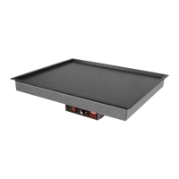
SET Key
Up Arrow
Key
Down
Arrow
Key
Display
Digital Temperature Controller
Changing Fahrenheit and Celsius Setting — Digital
Temperature Controller
Use the following procedure to change between Fahrenheit
and Celsius on the display.
1. Press the key once. Either an “F” for Fahrenheit or
“C” for Celsius will be displayed.
2. Press the key or key within 10 seconds to
change between “F” (Fahrenheit) and “C” (Celsius).
3. Press the key three times to lock in the new setting.
The TEMPERATURE display will go blank for two seconds
to show that the new setting has been accepted.
NOTE:After10secondsofinactivityduringtheprogramming
process, the controller will exit programming mode
automatically without saving any changes.
4″ (102 mm) Adjustable Legs (GRS Models)
Use the following procedure to install 4″ adjustable legs on a
GRS model.
NOTE:4″ (102 mm) legs are standard on models 36″
(914mm)andwider.
The National Sanitation Foundation (NSF) requires that
units over 36″ (914 mm) in width or weighing more than
80 lbs. (36 kg) either be sealed to or raised above
installation surface. If unit cannot be sealed at the point
of use, 4″ (102 mm) legs are included to allow for proper
cleaning access below unit.
1. Turn off the unit, unplug the power cord, and allow the unit
to cool.
NOTICE
Do not lay unit on the side with the control panel. Damage
to unit could occur.
2. Carefully turn the unit upside down and lay the unit on a
flat surface. Make sure to cover the surface with something
to prevent scratching the unit.
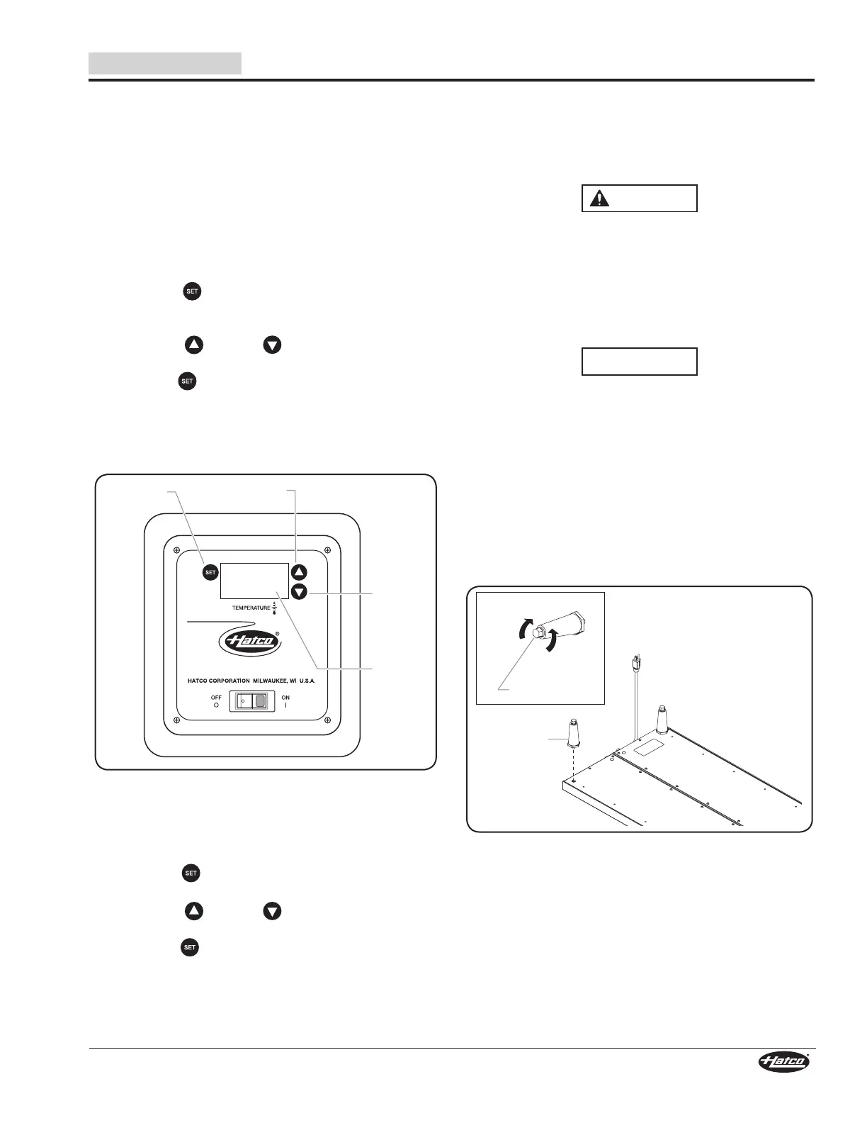
3. At each corner, thread a 4″ leg into the bottom of the unit.
Hand-tighten until snug. Do not over-tighten.
4. Return the unit to the upright position.
NOTE:Thefeetonthe4″legsareadjustableforlevelingthe
unit.Usea9/16″(14mm)open-endwrenchtomake
levelingadjustmentsoncetheunitisplacedinitsfinal
position.
102 mm (4″)
Leg
Lengthen
Shorten
Adjustable Foot
Leg Installation
Rubber Feet (GRS Models)
Rubber feet are available as accessories and are 3/8”
(10 mm) in height. Rubber feet allow the shelf to be closer to
the countertop.
Recessed Thermostat
A recessed thermostat is available as a factory installed option.
A recessed thermostat uses a plug to restrict adjustment of the
thermostat.
 Loading...