Do you have a question about the Haulotte Group OPTIMUM 8 and is the answer not in the manual?
Explains symbols used in the manual to convey safety information and warnings.
Details various decals used on the machine and their meanings, relating to safety and procedures.
Outlines essential safety practices for operating and maintaining the equipment.
Emphasizes the need for trained personnel and outlines responsibilities for maintenance.
Details the terms, conditions, and coverage provided under the product warranty.
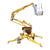
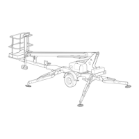
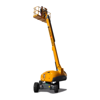
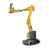
Identifies and illustrates the main parts of the machine for user understanding.
Describes the layout and controls of the ground control box, including the Activ'Screen.
Explains the layout and indicators of the platform control box.
Details the placement of various sensors and actuators on the machine.
Lists and identifies consumable parts required for the machine's operation.
Specifies the type and requirements for hydraulic oil used in the machine.
Illustrates the points requiring lubrication and the type of lubricant to use.
Provides key technical specifications, including movement speeds of the machine.
Presents a periodic maintenance plan based on time or operating hours.
Outlines the different types of inspections required and their frequency.
Details the checks to be performed by the operator before each use.
Describes the thorough inspection process required at regular intervals.
Covers the requirements for a more in-depth inspection of the machine structure.
Specifies the procedures for a comprehensive major inspection of the machine.
Details the visual checks for structural integrity performed daily.
Outlines the procedure for a thorough structural inspection including welding checks.
Describes tests to verify the proper functioning of structural components.
Provides recommendations for checking pins, bushes, and bearings.
Details the correct steps for reassembling pins and bearings after maintenance.
Describes routine visual checks for hydraulic cylinders.
Outlines tests to verify the proper operation of hydraulic cylinders.
Details the procedure for a comprehensive inspection of hydraulic cylinders.
Explains how to perform functional tests on the machine's brake system.
Provides torque specifications for metric fasteners used on the machine.
Lists torque specifications for SAE fasteners used in the machine.
Specifies torque values for sub-assemblies on the OPTIMUM 8 / 1930 E.
Details the procedure for inspecting hydraulic hoses for condition and leaks.
Outlines the safety precautions and steps for disassembling hydraulic hoses.
Guides on the correct procedure for reassembling hydraulic hoses and checking connections.
Lists the tools and equipment required for electrical wiring inspection and maintenance.
Explains how to check and adjust hydraulic system pressure.
Outlines the routine checks for scissor arm screws.
Details the procedure for tightening scissor arm screws using a torque wrench.
Details the steps for safely removing the steering pivot assembly.
Provides instructions for correctly reinstalling the steering pivot assembly.
Details the procedure for safely removing the platform assembly from the machine.
Provides instructions for correctly reinstalling the platform assembly.
Details the procedure for safely removing the scissor pack.
Provides instructions for correctly reinstalling the scissor pack.
Explains the step-by-step process for calibrating the steering system.
Outlines the process for calibrating the arm angle sensors for load management.
Provides an overview of the main menu structure for the Activ'Screen system.
Details the submenus and options available within the Activ'Screen system.
Offers general recommendations and a structured approach to diagnosing malfunctions.
Lists and describes specific failure codes, their causes, and potential solutions.
Explains the symbols and markings used in the control box overview.
Illustrates the overall system architecture and component connections.
Details the machine's electrical power circuit diagram.
Details the machine's electrical control circuit diagram.
Provides a comprehensive schematic of the machine's electrical system.
Presents a schematic diagram of the machine's hydraulic system.
A logbook for recording maintenance and repair activities.
| Brand | Haulotte Group |
|---|---|
| Model | OPTIMUM 8 |
| Category | Boom Lifts |
| Language | English |