3
FAN INSTALLATION :
For installation of Fan with downrod,the following instructions and methods are
to be followed.
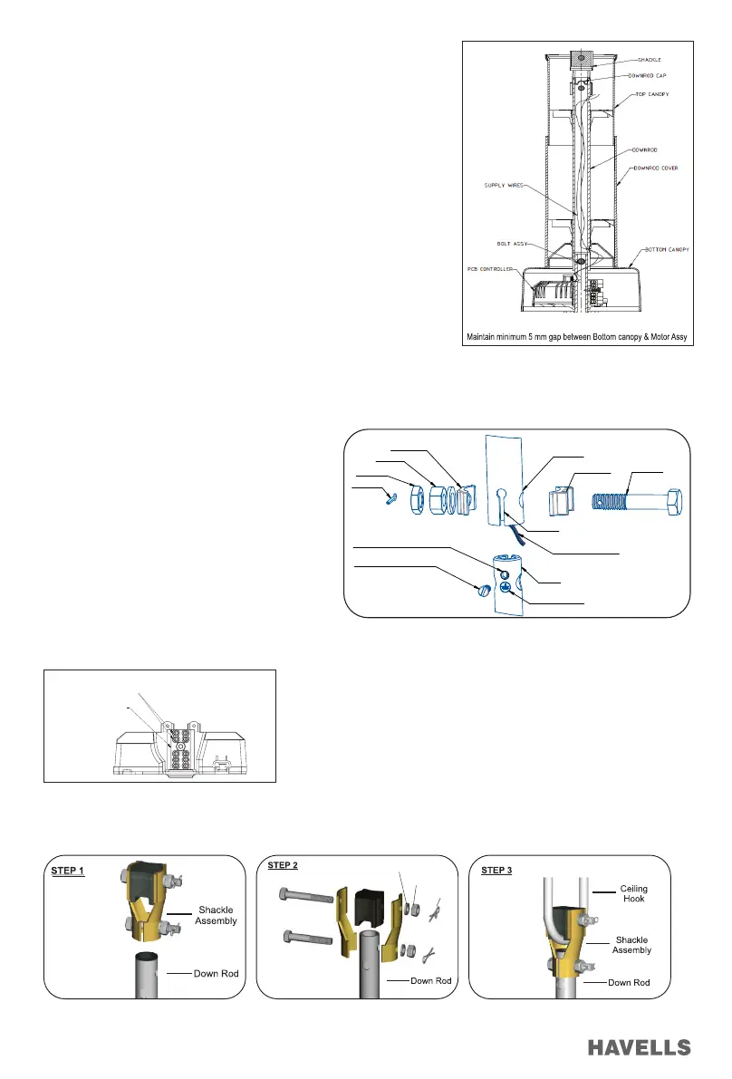
1. Remove the downrod cap from downrod and slide the bottom canopy over
the downrod and then slide top canopy from topside.
2. Pass the Power supply & earthing wires (to be installed by customer at
their end) through the downrod from top side holes and pull the wires from
slit hole of the downrod.
3. Remove the split pin, hex nut,lock nut,spring washer,aluminium spacers
from the bolt assembly supplied with the shackle assembly (Figure 5).
Remove the safety/earthing screw on the shaft and keep it securely
4. Slide the downrod (from split end side) over the shaft.Align the cross holes
on the downrod and the shaft.
5. Now use one Aluminium spacer on each side of the down rod for gripping
and insert the bolt,place the spring washer and tighten the hex nut and the
lock nut and tighten them fully,holding the bolt head with a spanner.
6. Ensure that this bolt is fully tighten. Insert the split pin and separate the
projected ends.
7. Fix the earthing wire to safety/earthing screw and tighten the safety screw
to shaft over down rod which was removed previously
8. The shackle assembly provided has hex bolt with hex nuts, lock nuts and
split pins. When hanging the fan on the hanger the hex bolts should be
securely tightened with hex nuts & lock nut.
9. The split pins should be securely replaced in their
place as shown in, assembled and exploded views
(Figure 4 & Figure 5)
Figure. 3Figure. 2 Figure. 4
Figure. 5
BOTTOM CANOPY
TOP CANOPY
DOWNROD CAP
DOWNROD
DOWNROD COVER
Sprint Washer
Hex Nut
Split Pin
Figure. 6 Figure. 7 Figure. 8
Installation of Fan with Ceiling Hook:
1. Steps to mount fan on ceiling hook as shown below:
Internal Wiring Connection (Figure 6):
1. Connect the Power supply wires (1 N) to the Terminal Connector.
SUPPLY WIRES
TERMINAL CONNECTOR
Figure 4
HEX BOLT
AL. SPACER
DOWNROD
SHAFT
AL. SPACER
HEX NUT
LOCK NUT
SPLIT PIN
SAFETY / EARTHING SCREW
SAFETY / EARTHING SCREW HOLE
SLIT HOLE
POWER SUPPLY WIRES
EARTHING SYMBOL
Figure 5
SUPPLY WIRES
TERMINAL CONNECTOR
Figure 6
 Loading...