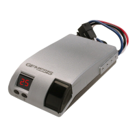
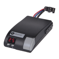
Electronic Brake Controller
Hayes BRAKE CONTROLLER P/N 81792K
OPERATIONS MANUAL
For trailers with 2-8 electric brakes and vehicles
with 12 volt negative ground systems only.
READ AND SAVE THESE INSTRUCTIONS
» Before beginning installation, read and become familiar
with these instructions.
» Leave in tow vehicle for future reference.
» IMPROPER INSTALLATION AND OPERATION
COULD CAUSE PERSONAL INJURY, AND/OR
EQUIPMENT AND PROPERTY DAMAGE.
TIP:
Recommended use with the HBCC
dual-mated harness for best results.
WARNING
Indicates a potentially hazardous situation that,
if not avoided, could result in death or serious
personal injury.
CAUTION
Indicates a potentially hazardous situation that,
if not avoided, could result in damage to
product or property.
TIP
Contains helpful information to facilitate
operation.
SAFETY SYMBOLS
1. AUTOMATIC OPERATION
During braking, the G2 senses deceleration of the tow vehicle.
An internal sensor measures the amount of deceleration and
sends a proportional amount of power to the trailer brakes.
The maximum braking supplied depends on the set up of the
controller. The LCD display will indicate the amount of power
being sent to the trailer brakes. Once the brake pedal is
released, the unit will remain in the “MAIN SCREEN.” While
standing by and during braking, the controller will display the
MAIN SCREEN: % power, voltage bar graph, brake type
(electric or hydraulic) and selected Boost setting (B0-B4).
Further explanation of the display is included in this document
ELECTRIC
50%
B2
E
1.1 LCD Display
The LCD display shows various symbols and numbers that are
used for set up and to monitor the trailer brake performance. It
is also used when troubleshooting.
1.2 Definitions of Options
WARNING:
Improper adjustment of the controller could
result in loss of trailer brakes, aggressive,
grabby, pulsating, or delayed trailer brakes.
Power adjustments may be required based upon speed,
trailer load, and road conditions.
Maximum trailer braking occurs just prior to lockup of the trailer
wheels.
Trailer brake lockup could cause loss of control of the trailer
and/or the tow vehicle.
1.3 Main Screen
» During braking conditions - the Main Screen displays
the % of power, Boost setting, Brake Type and
power/voltage (bar graph) being applied to the trailer
brakes.
» The controller is factory pre-set to 50% of maximum power.
The scale for the power is 10% to 100%.
» The BRAKE TYPE is factory pre-set to Electric. For
hydraulic actuated brakes, the BRAKE TYPE must to set
to Hydraulic). The selected BRAKE TYPE is displayed
ELECTRIC or HYDRAULIC at the top of the Main Screen.
» The BOOST is factory pre-set to B2 (10%).
Maximum Power (for Automatic braking only):
The controller is factory pre-set to 50% of maximum power.
When the controller senses maximum deceleration, the most
power that the controller will send to the trailer brakes will be
50%.
Changing Maximum Power for Automatic operation
only (Manual operation is not affected)
Note: To change the maximum power level, the controller
must be in “normal” operating mode. If the Main screen is not
being displayed, see the supplied Screen Menu for directions.
The maximum power setting under non-braking conditions
may be changed as follows:
1. With the vehicle at rest, press the “up” or “down” button
and the LCD display will shows the existing maximum
power setting in a percentage format (i.e. 50%).
2. To increase the maximum power setting, press and release
the “up” button. The current maximum power setting will be
increased by 5%. Continue to press and release the “up”
button to increases the maximum output to the desired
level. Press the “enter” button to save this setting or wait a
few seconds and the displayed setting will be saved as the
maximum output. The Main Screen will return and display
actual outputs.
3. To decrease the maximum power setting, press and
release the “down” button. The current maximum power
setting will be decreased by 5%. Continue to press and
release the “down” button to decreases the maximum
output to the desired level. Press the “enter” button to
save this setting or wait a few seconds and the displayed
setting will be saved as the maximum output. The Main
Screen will return and display actual outputs.
Notes:
A. While the vehicle is moving, the maximum power setting
can be changed as shown above. This procedure is not
recommended if driving in traffic. This should be done in
a deserted parking lot or another suitable place with no
traffic.
B. After a few hours of being inactive (with or without a
trailer connected), the display will go blank. While the
display is blank, very little power will be used by the G2.
2. BOOST SETTINGS:
(for Manual and Automatic operation)
The controller is factory pre-set to a Boost Setting of B2
(10%). At this setting, the MINIMUM amount of power that
will be immediately applied to the trailer brakes is 10% (when
the brake pedal is depressed and before deceleration is
detected). The selected Boost setting controls the minimum
power in automatic and manual operation (as a percentage of
total available power).
Changing Boost Setting (Manual and Automatic)
Changing the Boost setting is designed to allow more or less
power to be delivered to the brakes when the controller does
not sense deceleration. See the section for loaded trailer
weight guidelines and select the Boost setting required for
your loaded trailer weight.
The Boost setting may be changed in 5% increments
(B0 = off, B1 = 5%, B2 = 10%, B3 = 15%, and B4 = 20%)
To do this, follow these steps:
1. With the vehicle at rest, push the “enter” button while
on the Main Screen (if not on the Main Screen, see the
supplied Screen Menu for directions). This will pull up the
SETTUP screen.
2. Press the “down’ button until the curser is on Boost
Mode.
3. Press the “enter” button and the BOOST MODE
screen will be displayed.
4. Move the curser up or down using the “up” or “down”
key until the curser rest on the desired Boost setting.
5. Press the “enter” button to select the desired boost
setting. The new Boost setting is now set.
Note:
The higher the Boost setting the more aggressive the
braking. A setting of B0 and B1 will delay the braking
output a small amount.
3. BRAKE TYPE:
Most trailers have electric brakes, but some have Electric
over Hydraulic brakes. The Electric over Hydraulic brakes
should not be connected to a brake controller that checks
the electrical connection. For this reason, G2 brake
controller needs to know the type brakes that are
connected.
Changing the Brake Type:
Most trailers have electric brakes, but some have Electric
over Hydraulic brakes. The following will describe how to
change between Electric Brakes and Electric over
Hydraulic brakes.
1. Enter the SETUP screen and select Brake Type. This
will pull up the Brake Type screen.
2. Select the Brake Type that best describes your trailer
(Electric or Hydraulic).
3. You will have to Accept to store your brake type and
return to the Setup screen.
Note:
If the WARNING/NO TRAILER screen is displayed all
the time, you must change the brake type to Hydraulic if
this is the correct type of trailer brakes. See above for
directions.
4. Audible Alarm Mode:
The G2 brake controller has an audible alert for faults. This
function can be turned off if not wanted. The default is for
the audible alert to be set to ON.
Changing audible Alarm Mode (Manual and
Automatic)
To do this, follow these steps (If not on the Main Screen,
see the supplied Screen Menu for directions):
1. While at the Main Screen push the “enter” button to
enter the setup screen, push the ‘down” button until
Alarm Mode is highlighted.
2. To turn the audible alert off select Alert OFF and push
the “enter” button. This will return you to Setup screen
and prevent the audible alert from being activated when
a fault is detected.
3. To turn the audible alert on, follow the above
instructions only select Alert ON.
4. Push the enter button and audible Alert ON is selected
and the screen is returned to Setup screen.
5. Manual Slide Lever Operation
» The “Manual Slide Lever” (Fig. 2) is located on the
bottom of the controller.
» The further the manual slide lever is moved toward the
front of the controller, the greater the amount of trailer
braking power.
» The manual slide lever operation is an independent
circuit and overrides the maximum power setting to
allow full braking power when required.
» The manual slide lever is used to apply the trailer brakes
independently of the tow vehicle brakes or to override
the automatic trailer brakes when more braking is
required.
TIP:
It is normal to hear the trailer brake magnets “hum”
when operating the trailer brakes.
WARNING:
Manual operation via the manual slide lever may
not disengage the Cruise Control on some
vehicles
6. TROUBLESHOOTING IN AUTOMATIC AND
MANUAL MODES
To verify the brake controller is properly wired, follow these
steps:
A. With the trailer connected to tow vehicle and vehicles
at rest, make certain that the brake controller is set to
the correct BRAKE TYPE (reference screen menu
sheet).
B. From the SETUP screen, select Diagnostics. From
the DIAGNOSTICS screen, select Troubleshoot. From
the TROUBLESHOOTING screen, Battery Volts,
Stoplight Volts, Output Volts and Output Amps may
be selected for checking.
C. Select Battery Volts. Tow vehicle battery voltage will be
displayed on the BATTERY VOLTAGE screen.
D. Select Stoplight Volts. Voltage to the stoplights will be
indicated on the STOPLIGHT VOLTAGE screen as either
On or Off. To check for proper operation, apply enough
pressure to the tow vehicle brake pedal to activate the
stop lights. If the STOPLIGHT VOLTAGE screen
indicates On, the brake controller red lead has been
connected to the correct stop light circuit. With the brake
pedal released, pull the brake controller manual slide lever
toward the front of the controller. The STOPLIGHT
VOLTAGE screen should also indicate On.
E. Select Output Volts. Pull the manual slide toward the
front of the controller. The OUTPUT VOLTAGE screen
will indicate a voltage that will vary from approximately
10% to nearly 100% of battery voltage depending on the
position of the manual slide control.
F. Select Output Amps. Pull the manual slide toward the
front of the controller. The OUTPUT CURRENT screen
will indicate a current (amps) that will vary in accordance
with the number of trailer brakes and the position of the
manual slide control. With the manual slide control full on,
each brake coil should draw approximately 3 amps. making
this feature useful for determining if the total current draw
of the trailer is within a proper range. This current reading
may vary significantly due to the temperature of the brake
coils.
6.1 Road Test and Performance Adjustment
To set the controller up for optimum performance with your
tow vehicle / trailer combination, follow these steps:
A. Position the tow vehicle and trailer on a hard, flat, dry
surface.
B. Set the controller display to the Main Screen.
C. When shipped from the factory, the controller's Output
power is set to 50% and the Boost setting is 10% (B2).
For changing the Output power setting, refer to
"Changing Maximum Power" section of this manual.
6.2 Troubleshooting Using the display
The G2 will display warning screens to indicate problems with
the trailer, tow vehicle or brake controller.
Short Circuit:
TIP:
Warm trailer brakes tend to be more responsive than
cold brakes.
CAUTION:
In the automatic mode and Boost setting of B0,
B1 or B2, the trailer brakes are applied only
when the sensor detects deceleration.
With the vehicle at rest and the brake pedal depressed,
there should be no or slight output to the trailer brakes
(when minimum power is set to B0, B1 or B2).
Higher at rest outputs and reverse braking can be obtained
by increasing the Boost setting to B3 or B4.
If the Loaded Trailer weight is... Then set the Boost to:
Much less than the tow vehicle B0 or B1
Less than the tow vehicle B2
Roughly equal to the tow vehicle B2 or B3
Slightly greater than the tow vehicle B3 or B4
Much greater than the tow vehicle B4
This indicates that the controller has sensed a direct short
between the controller’s output and ground. This condition
must be cleared before the controller is used. It is
usually an indication that a “hot” wire is connected to ground.
Current Limit:
This indicates that the controller has sensed a power
requirement greater than its maximum rated output but not a
direct short. When this occurs, the controller will continue to
supply full current (up to the maximum rating),however, the
controller will begin to limit this current above this level. This
could result from an intermittent short to ground in the trailer
wiring, a faulty brake coil, or too many brake coils connected
to the controller.
Open Circuit:
BLUE WIRE FAULT
Voltage Present
WARNING
OUTPUT SHORT
No Brakes
WARNING
OVERLOAD
Excessive Amps
WARNING
NO TRAILER
WARNING
LCD Display
Setup
Adjustment
Buttons
Manual Override
Slide Lever
» The manual slide lever is used in emergency stop situations
when more braking may be required than is available with
the maximum power setting or for control of excessive
trailer sway.
» The tow vehicle and trailer brake stoplights will be
illuminated during the manual lever activation.
For changing the minimum or Boost level, refer to
"Changing Boost Setting"section of this manual.
D. Accelerate to approximately 25 mph and apply the brakes
in a normal manner. The vehicle should come to a stop
without the trailer “pushing” the tow vehicle. A firm braking
action should occur.
E. If the trailer brakes lock, decrease the Output power level.
F. If more braking power is needed, increase the Output
power level.
G. Repeat this process until the desired amount of braking is
achieved.
H. If needed, follow the instructions in the “Changing Boost
Setting” section to increase or decrease the minimum
power. The following guidelines should be used as a
starting point for selecting this option:
This is an indication that there is no trailer connected to
the tow vehicle. The display can be cleared by pressing
any button on the controller or connecting a trailer.
Connection to electric over hydraulic trailer brakes can
also cause this screen to be displayed. If this occurs, the
Brake Type must be changed from Electric to Hydraulic.
Refer to Screen Menu.
Blue Wire Fault:
This warning will be displayed when external voltage is
detected on the blue wire. Removing the external voltage
will clear the display. Possible causes can be the blue
wire being connected to the wrong place, a short in the
wiring or the connector, or a faulty or disconnected
breakaway switch.
CAUTION:
In the automatic mode and Boost setting of B0,
B1 or B2, the trailer brakes are applied only when
the sensor detects deceleration.
With the vehicle at rest and the brake pedal depressed,
there should be no or slight output to the trailer brakes
(when minimum power is set to B0, B1 or B2).
Higher at rest outputs and reverse braking can be obtained
by increasing the Boost setting to B3 or B4.
fig. 1 Front View
fig. 2
Boost Setting Guidelines for Different Trailer Weights
(continued below, far left)
Main Screen
LCD Display
 Loading...