Controller and Bracket Mounting
» The controller must be mounted with the back of the
controller toward the front of the vehicle.
» Use the reversible slotted mounting bracket.
» Do not mount the controller upside down or sideways.
Installation Steps
1. Install the mounting bracket to a solid surface
under the tow vehicle dash using the two machine
screws and fasteners provided. Tighten until snug.
See fig. 3 Attachment of Mounting Bracket
2. Insert four of the self-tapping screws provided
through the mounting bracket holes and into the
desired controller anchor holes. Tighten until snug.
3. Mount in a location which allows the driver to easily
apply the manual override and see the Red
Indicator Light.
Read all wiring instructions completely
before you begin wiring the controller to
the tow vehicle.
Controller Wiring Instructions
WARNING:
If the controller is mounted incorrectly, the
deceleration sensor arm cannot operate
correctly and may cause loss of braking.
WARNING:
All four controller wires must be connected
properly for the controller to operate
correctly.
Failure to properly connect all four wires can cause
loss of trailer braking.
Improper wiring will destroy the controller and void
the manufacturer’s warranty.
CAUTION:
Care must be taken to ensure that the
mounting surface is rigid enough to
prevent excessive vibration.
Excessive vibration may result in poor performance.
WARNING:
To reduce the risk of injury or damage to
property:
» Always connect the white wire first and the
black wire second.
» All four controller wires must be connected
properly for the controller to operate correctly.
» Failure to connect the wires correctly can cause
loss of trailer braking.
WARNING:
The white wire must be connected to a
known good ground (preferably the
negative battery post).
controller and void the manufacturer’s warranty.
WARNING:
Improper connections may result in no
trailer brakes or destroy the controller
technical suppo
latest controller red stoplight wire to stoplight
switch connections.
WARNING:
Follow wiring instructions.
Improper wiring will destroy the
controller and void the manufacturer’s warranty.
READ AND SAVE THESE INSTRUCTIONS
» Before beginning installation, read and become
familiar with these instructions.
» Leave in tow vehicle for future reference.
» IMPROPER INSTALLATION AND OPERATION
COULD CAUSE PERSONAL INJURY, AND/OR
EQUIPMENT AND PROPERTY DAMAGE
Mounting Angles
Mounting angles between -35 and + 90 degrees can
be accommodated by the controller. THE UNIT MUST
BE INSTALLED SO THAT IT IS PARALLEL WITH THE
TRAVEL OF THE TOW VEHICLE AND TRAILER.
Controller Mounting and Installation
Controller and Universal Quik-Receiver
®
» The Universal Quik-Receiver provided is to be used
for mounting the controller to the tow vehicle.
» DO NOT MOUNT CONTROLLER UPSIDE DOWN
OR SIDEWAYS.
CAUTION:
In the automatic mode, noticeable braking
is applied only when the deceleration
sensor detects deceleration. With the vehicle at rest
and the brake pedal depressed, there should only be
slight output to the trailer brakes.
WARNING
Indicates a potentially hazardous situation
that, if not avoided, could result in death or
serious personal injury.
CAUTION
Indicates a potentially hazardous situation
that, if not avoided, could result in damage to
product or property.
TIP
Contains helpful information to facilitate
installation.
SAFETY SYMBOLS
Installation Steps
1. Install the Universal Quik-Receiver to a solid surface
under the tow vehicle dash using the two machine
screws or VHB high bonding tape applied to the
Universal Quik-Receiver.
See fig. 2 Acceptable Mounting Angles and fig. 3
Attachment of Universal Quik Receiver.
2. Mount in a location which allows the driver to easily
apply the manual override and see the digital display.
WARNING:
All four controller wires must be connected
properly for the controller to operate correctly.
Failure to properly connect all four wires can cause
loss of trailer braking.
Improper wiring will destroy the controller and void
the manufacturer’s warranty.
WARNING:
To reduce the risk of injury or damage
to property:
» Always connect the white wire first and the
black wire second.
» All four controller wires must be connected properly
for the controller to operate correctly.
» Failure to connect the wires correctly can cause
loss of trailer braking.
WARNING:
If the controller is mounted incorrectly, the
three axis accelerometer cannot operate
correctly and may cause loss of braking.
CAUTION:
Care must be taken to ensure that the
mounting surface is rigid enough to
prevent excessive vibration.
Excessive vibration may result in poor performance.
WARNING:
The white wire must be connected to a
known good ground (preferably the negative
battery post).
Improper or no ground will result in poor controller
performance or lack of performance altogether.
Improper ground connection can destroy the controller
and void the factory warranty.
WARNING:
Improper connections may result in no
trailer brakes or destroy the controller and
void the manufacturer’s warranty.
WARNING:
Follow wiring instructions.
Improper wiring will destroy the controller
and void the manufacturer’s warranty.
CAUTION:
DO NOT connect the black wire to any
vehicle power supply line or fuse panel
that could cause circuit overload or damage to
tow vehicle wiring and vehicle electronics.
Route the black wire through a grommet hole
in the fire wall to prevent grounding and away
from the radio antenna to reduce any possible
AM radio interference.
Controller Wiring Instructions
Leveling the G2 Controller
1. The G2 is self leveling.
2. When the brakes are first applied, the G2 will
read the level position before actual braking begins
and apply the brakes proportional to the
deceleration.
Read all wiring instructions prior to making
electrical connections to the tow vehicle.
WARNING:
All 1999 and later Ford vehicles
without the trailer wiring package:
The red controller wire must be connected to the
light green wire of the brake stoplight through a
20-amp in-line fuse.
Failure to install a 20-amp in-line fuse can
destroy the controller and void the
manufacturer’s warranty.
WARNING:
1989—1991 Ford Bronco, Econoline,
F-Superduty, and F150-350 Series:
The red stoplight wire MUST splice into the turn
signal connector harness and NOT in the
stoplight switch.
Connecting to the terminal of the stoplight
switch will break the switch and result in no
stoplights and no trailer braking.
Vehicle Mechanical
Stoplight Switch
SW
Non-Powered Stoplight Wire Stoplights
20 Amp In-line Fuse
(not furnished)
20A
Ground
Red
Black
White
Blue
Trailer Brakes
Trailer Ground
Use Self-Reseting
Circuit Breaker
See Chart for Size
(not furnished)
Chassis/Ground(-)
Negative
Positive
(+)
Tow Vehicle/Trailer
Electrical Connector
CB
12 Volt
Battery
Brake
Controller
Important:
Make all controller wiring connections to the wiring
harness before connecting the harness to the
vehicle.
The following chart describes the function of each of the controller’s wires:
1
st
White Ground 16 Grounded metal part of firewall or directly to
the negative (-) terminal of the battery.
Connect this wire first.
2
nd
Black + Connection to the 12 Positive (+) terminal of the battery. MUST have
vehicle’s power a self-resetting Circuit Breaker in-line between
system the controller and the battery. See chart for
proper size. Route the black wire through a
grommet hole in the firewall to prevent wire
grounding and away from the radio antenna
to reduce any possible AM radio interference.
Connect this wire second.
3
rd
Red Stoplight 14 Non-powered stoplight wire (of the stoplight
switch) or trailer tow wiring harness. It is
recommended that a 20-amp in-line fuse
be installed between the controller’s red wire
and the stoplight switch. The fuse is
required in 1999 & later Fords.
4
th
Blue Output to trailer brakes 12 The trailer brake wire or tow vehicle/trailer
connector.
Order: Color: Function: Wire Size Connect to:
(AWG):
Number of Brake Light Bulbs
(tow vehicle Plus trailer)
4 Bulbs (minimum)
5 Bulbs
6 Bulbs
7 Bulbs
8 Bulbs
9 Bulbs
Number of Trailer Brakes
2 Brakes
20 AMP
20 AMP
20 AMP
30 AMP
30 AMP
30 AMP
4 Brakes
30 AMP
30 AMP
30 AMP
30 AMP
30 AMP
40 AMP
6 Brakes
30 AMP
30 AMP
40 AMP
40 AMP
40 AMP
40 AMP
8 Brakes
40 AMP
40 AMP
40 AMP
40 AMP
50 AMP
50 AMP
Self-Resetting Circuit Breaker Size Chart. NOTE: Each trailer brake magnet is assumed to draw 3 amps of
current and each brake lamp bulb is assumed to draw 2 amps.
Special Conditions
For tow vehicles equipped with factory trailer-
towing package:
» Refer to your vehicle owner’s manual to determine the
correct connection points for the controller.
For vehicles without a trailer-towing package:
» Refer to the wiring diagram in fig. 4.
fig. 4
TIP:
Recommended use with the HBCC
dual-mated harness for best results.
G2
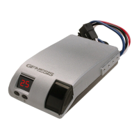
fig. 1 Front View
LCD Display
Setup
Adjustment
Buttons
Manual Override
Slide Lever
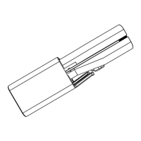
fig. 3 Attach Universal Quik-Receiver to Vehicle Dash
fig. 2 Acceptable Mounting Angles
Front of Vehicle
-35˚ to 90˚
Universal Quik-Receiver
Attach Universal
Quik-Receiver
to vehicle dash
Insert G2 into
Universal
Quik-Receiver
TIP:
Special Dual-Mated “Quik-Connect”
Wiring Harnesses are available for all
Hayes Brake Controllers fitted with a connector
on the wire leads, making connection a snap.
Harnesses are available through all dealer
resources.
Electronic Brake Controller
Hayes BRAKE CONTROLLER P/N 81792K
INSTALLATION MANUAL
For trailers with 2-8 electric brakes and vehicles
with 12 volt negative ground systems only.