MAINTENANCE
17
F−96498
ENGINE MAINTENANCE
Use the following maintenance section to keep
your unit in good operating condition. All the
maintenance information for the engine is in
the “Engine Instruction Book”. Before you start
the engine, read this book.
WARNING: Before you make an
inspection, adjustment (except
carburettor), or repair, discon-
nect the wire from the spark
plug.
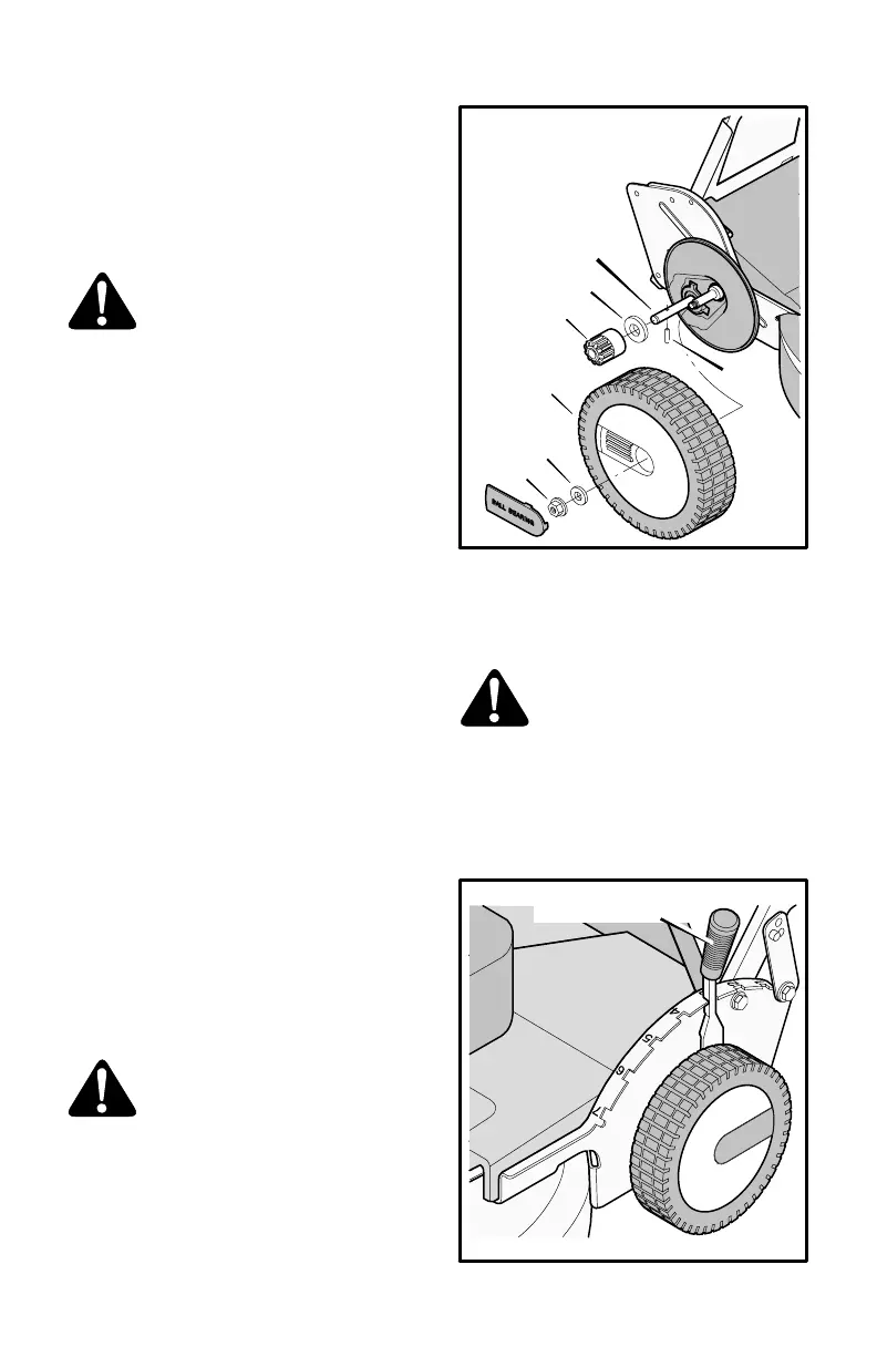
LUBRICATION
1. Lubricate the drive bearings on each end
of the drive shaft as follows.
Remove the rear wheel and the pinion
gear (Figure 9).
Clean the inside of the wheel and the
pinion gear of dirt and debris.
Lubricate the drive shaft and the in-
side of the pinion gear with Permatex
Anti−seize lubricant or a dry graphite
spray lubricant. In non−sandy areas,
standard grease is acceptable.
Assemble the pinion gear and the rear
wheel.
2. For maximum performance, lubricate the
wheels and all pivot points with engine oil
every 25 hours.
3. To lubricate the engine, see the instruction
book for the engine.
NOTE: Do not lubricate the engine stop
cable. Lubricants will damage the cable
and prevent the cable from moving freely.
Replace the cable if bent or damaged.
HOW TO CLEAN
THE MOWER HOUSING
WARNING: The blade will rotate
when the engine runs. Before
you clean the mower housing,
stop the engine and disconnect
the wire from the spark plug.
Grass and other debris can keep the mower
from working correctly. After you mow, clean
the mower housing as follows.
1. Stop the engine.
2. Disconnect the wire from the spark plug.
Thrust Washer
Pinion Gear
Pin
Drive Shaft
Rear Wheel
Washer
Nut
Figure 9
3. Clean the top and the bottom of the mower
housing.
HOW TO ADJUST THE HEIGHT OF CUT
WARNING: The blade will rotate
when the engine runs.
To change the height of cut, move the position
of the adjuster arm (Figure 10).
1. Disengage the adjuster arm.
2. Move the adjuster arm to another posi-
tion.
Figure 10
Height Adjuster