V. INSTALLATION GUIDE
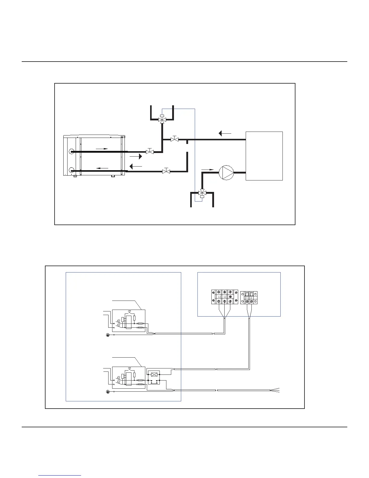
1. Diagram for Water Piping Connections
2. Electric Wiring Diagram
7
Note: The diagram is for demonstration purposes only, and layout of the pipes is for reference only.
Note: The swimming pool heat pump must be grounded.
Breaker/fuse
(Customer prepare)
Earthing
Power Supply
230V/ 60Hz
L1
L2
Breaker/fuse
(Customer prepare)
Earthing
Power Supply
230V/ 60Hz
L1
L2
Pump
Heat Pump
contactor
Terminal Board
Users'Electric Box
Ground
Terminals
Ground
Pump
POOL WATER IN
WATER TO SWIMMING POOL
STOP VALVE
THREE WAY
VALVE
SWIMMING
POOL WATER
TREATMENT
SYSTEM
work together
STOP VALVE
STOP VALVE
THREE WAY
VALVE
FILTER
Outlet Valve
Inlet Valve
By-Pass Valve
V. INSTALLATION GUIDE
1. Diagram for Water Piping Connections
2. Electric Wiring Diagram
7
Note: The diagram is for demonstration purposes only, and layout of the pipes is for reference only.
Note: The swimming pool heat pump must be grounded.
Breaker/fuse
(Customer prepare)
Earthing
Power Supply
230V/ 60Hz
L1
L2
Breaker/fuse
(Customer prepare)
Earthing
Power Supply
230V/ 60Hz
L1
L2
Pump
Heat Pump
contactor
Terminal Board
Users'Electric Box
Ground
Terminals
Ground
Pump
POOL WATER IN
WATER TO SWIMMING POOL
STOP VALVE
THREE WAY
VALVE
Filter
work together
STOP VALVE
STOP VALVE
THREE WAY
VALVE
OUTLET
INLET
 Loading...