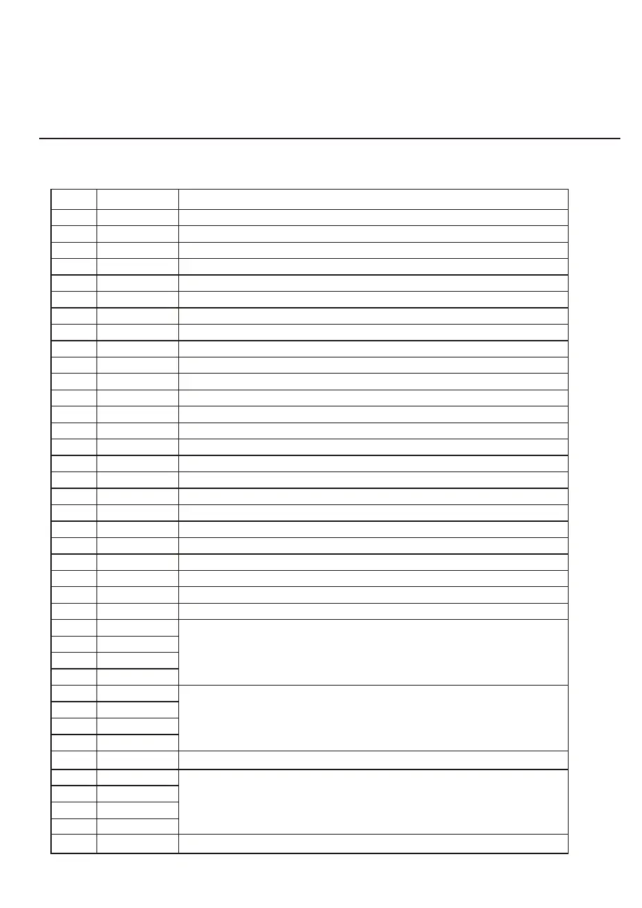
Connections explanation᧶
No.
1
2
3
4
5
6
7
8
9
10
11
12
13
14
15
16
17
18
19
20
21
22
23
24
25
26
27
28
29
30
31
32
33
34
35
36
37
38
39
Symbol Meaning
OUT1
OUT2
OUT3
OUT4
OUT5
AC-L
AC-N
AI/DI01
AI/DI02
AI/DI03
AI/DI04
AI/DI05
AI/DI06
AI/DI07
AI/DI08
AI/DI09
AI/DI10
AI/DI11
AI12(50K)
0_5V_IN
PWM_IN
PWM_OUT
0_10V_OUT
+5V
+12V
GND
485_B1
485_A1
12V
GND
485_B2
485_A2
12V
Cn9
GND
485_B3
485_A3
12V
FUSE
Compressor ( output 220-230VAC)
Water pump ( output 220-230VAC)
4-way valve ( output 220-230VAC)
High speed of fan ( output 220-230VAC)
Low speed of fan (output 220-230VAC)
Live wire ( input 220-230VAC)
Neutral wire ( input 220-230VAC)
Emergency switch (input)
Water flow switch (input)
System low pressure (input)
System high pressure (input)
System suction temperature (input)
Water input temperature (input)
Water output temperature ( input )
System fan coil temperature( input)
Ambient temperature( input)
Mode switch / coil 2 temperature(input)
Master-slave machine switch / Antifreeze temperature(input)
System Exhaust temperature (input)
Compressor current detection/Pressure sensor(input)
Master-slave machine switch / Feedback signal of EC fan ( input )
AC fan control ( output )
EC fan control ( output )
+5V ( output )
+12V ( output )
Frequency conversion board communications
Color line controller communication
Electronic expansion valve
The port for centralized control
T5AL250V
6.APPENDIX
17




 To Next Page