USE ONLY HAYWARD GENUINE REPLACEMENT PARTS
8
Wiring Connections
1. TURN OFF THE ELECTRICAL POWER AT THE CIRCUIT BREAKER.
2. Loosen the four screws securing the wiring compartment cover and remove the cover to gain access to the drive wiring compartment.
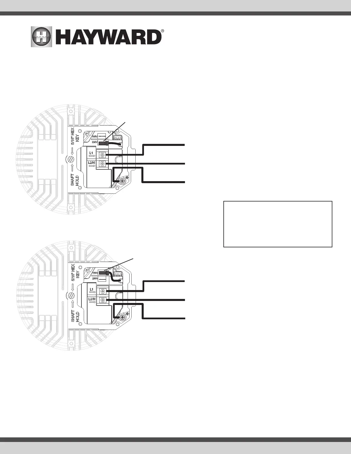
3. Move the selectable input voltage jumper to the appropriate position as shown below (comes set for 230 VAC from the factory). Pull the jumper straight
up off the connector to disconnect. Connect line power supply wiring to the appropriate terminals. Connect ground wiring to the ground screw. Exit wiring
must be routed through the conduit using proper watertight fittings.
4. Connect the pump to the pool bonding system as described on page 7. A lug for bonding is provided on the top of the motor.
5. After all electrical connections have been made, replace the wiring compartment cover, taking care to make sure it is properly aligned with the motor
drive. Tighten the four screws to secure. Note: The wiring compartment cover must be installed properly to provide environmental protection for the wiring
compartment.
115 VAC
L1
N
Ground
Jumper in 115 VAC position
230 VAC
L1
L2
Ground
Jumper in 230 VAC position
ATTENTION: ROUTE WIRING DIRECTLY FROM FIELD
CONDUIT TO TERMINAL BLOCK AS SHOWN. DO NOT
BUNDLE EXCESS WIRING INSIDE DRIVE ENCLOSURE.
-USE COPPER CONDUCTORS ONLY
- ACCEPTABLE FOR FIELD WIRING
- NOT SUITABLE FOR USE WITH RIGID METAL CONDUIT
- REMOVE TEST LEADS PRIOR TO INSTALL