EasyManua.ls Logo

Hayward SP23510VSP User Manual

Hayward SP23510VSP
32 pages
To Next Page IconTo Next Page
Page #1 background imageLoading...
Page #1 background image
IS23510VSP Rev-C
Hayward Pool Products
620 Division St, Elizabeth, NJ 07207
Phone: (908) 355-7995
www.hayward.com
MaxFlo VS
500
Owner’s Manual
Model SP23510VSP
MaxFlo VS 500 Variable Speed Pump
Hayward’s MaxFlo VS 500 variable speed pump delivers incredible energy savings via its advanced
hydraulic design combined with a totally enclosed, permanent magnet motor. The MaxFlo VS 500 pump
is easily installed either as a programmable stand-alone pump or with a Hayward or third party
controller and features an easy-to-use digital control interface that can be mounted in four different
positions on the pump or removed and mounted on the wall for total user convenience.
Note: To prevent potential injury and to avoid unnecessary service calls, read this manual carefully and
completely. Unless otherwise stated, instructions in this manual apply to both pump models.
SAVE THIS INSTRUCTION MANUAL
Question and Answer IconNeed help?

Do you have a question about the Hayward SP23510VSP and is the answer not in the manual?

Hayward SP23510VSP Specifications

General IconGeneral
BrandHayward
ModelSP23510VSP
CategoryWater Pump
LanguageEnglish

Summary

Important Safety Instructions

General Information

Introduction

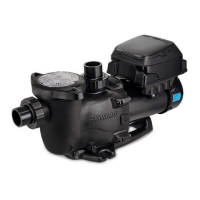
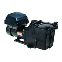
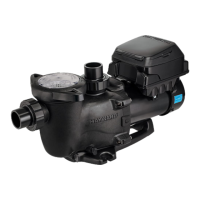
Manual provides information for proper installation and operation of the Hayward MaxFlo VS 500 Variable Speed Pump.

Primary Features

Lists the key features of the MaxFlo VS 500 pump, including motor type, hydraulic design, and control interface.

Product Dimensions

Presents dimensional data for the MaxFlo VS 500 pump with an accompanying diagram.

Energy Efficiency Overview

Installation and Wiring

Pump Location

Guidance on selecting an appropriate location for the pump, considering pool proximity and environmental factors.

Pump Mounting

Instructions for securely mounting the pump on a level, rigid base to minimize vibration and stress.

Pipe Sizing Chart

Recommended system flow rates based on pipe size and required straight pipe length.

Plumbing

Guidelines for connecting plumbing to the pump, including PTFE tape usage and fitting restrictions.

Electrical

Essential safety warnings and requirements for all electrical wiring and connections.

Electrical Specs

Details on voltage, amperage, and speed range for the pump's electrical requirements.

Voltage

Information on acceptable voltage variations and troubleshooting voltage issues.

Grounding and Bonding

Mandatory procedures for grounding and bonding the pump to prevent electrical shock hazards.

Wiring

Instructions for permanently connecting the pump to the circuit and managing shared circuits.

Remote Control Wiring/Operation

Methods for controlling the MaxFlo VS 500 using various remote control and third-party systems.

Digital Control Interface Orientation

How to adjust the orientation of the digital control interface for optimal viewing and access.

Interface Wall Mounting

Step-by-step guide for mounting the digital control interface on a wall using the optional kit.

Installation Procedure

Comprehensive steps to follow for the complete installation of the pump and its interface.

Wiring Diagrams

Input Power Wiring (Required)

Diagram illustrating the required connections for the pump's input power supply.

Wall Mounted Digital Control Interface Wiring (Optional)

Wiring diagram for optional wall mounting of the digital control interface.

External Relay Speed Control Wiring (For remote selection of pump speed)

Remote Stop Switch Wiring (Optional)

Startup & Operation

Prior to Start-Up

Pre-operational checks and safety precautions before starting the pump for the first time.

Starting/Priming the Pump

User Interface Summary

Menu Outline

Initial startup

Configuration Menu

Timer Menu

Preset Speed Setup Menu

Diagnostic Menu

Stop/Resume

Quick Clean

Remote Stop

Maintenance

Storage / Winterization

Storing Pump For Winterization

Detailed steps for properly storing the pump for winter to prevent damage and voiding warranty.

Shaft Seal Change Instructions

Removing the Motor Assembly

Procedure for safely removing the motor assembly from the pump housing.

Removing the Impeller

Steps to remove the pump impeller from the motor shaft.

Removing the Ceramic Seat

Instructions for removing the ceramic seat from the seal plate.

Seal Installation

Replacing the Impeller and Diffuser

Replacing the Motor Assembly

Replacement Parts

Parts Diagram

Visual diagram identifying all component parts of the pump with corresponding reference numbers.

Parts Listing

Troubleshooting

General Problems

Covers common issues like motor not starting, shutting off, or humming.

Check System Messages

Warranty

Related product manuals