920-0090-01 Rev C
Page 4 of 8
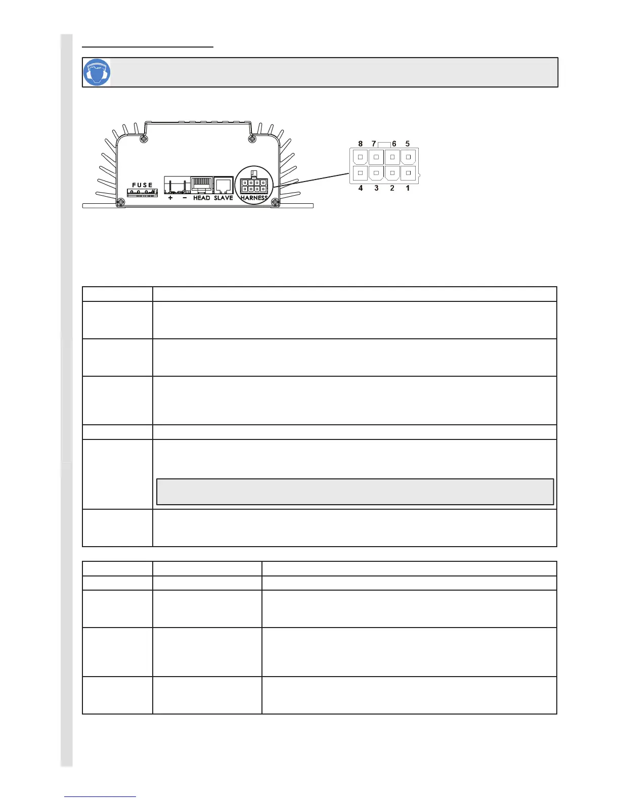
CS201 Electronic Siren
Amplifi er (Front View) Harness Connector (Front View)
Before proceeding with installation, plan all cable routing and wiring carefully.
The table below should be used in conjunction with the wiring diagram on page 6 to make all connections to the
siren.
PORT DESCRIPTION
FUSE
The amplifi er comes equipped with an ATO blade fuse in the FUSE location as shown above.
A 20 Amp fuse is used for 12 Volt or a 15 Amp fuse is used for 24 Volt systems.
+
Amplifi er Positive Terminal - connect to 3mm² (9 AWG) automotive wire using a 6.3mm (0.25”)
female spade fully insulated terminal. Do not connect this red power wire to the vehicle
battery terminal until all other connections have been made to the unit.
-
Amplifi er Negative Terminal - connect to a good chassis ground point or the battery negative
terminal, using the shortest possible wire length with a 3mm² (9 AWG) automotive wire and a
6.3mm (0.25”) female spade fully insulated terminal.
HEAD Connect the CS201 control head (via extension cable if used) to this port.
SLAVE
Optional slave siren port - connect to a slave siren unit to provide additional siren output.
Ensure all speakers are wired with same polarity. Do not connect the SLAVE port to the
HEAD port.
Important! Do not connect the SLAVE ports together until all other connections are made,
failure to do so may result in damage to the siren and harness.
HARNESS
A wire harness with an 8-way connector is provided to plug into this position – the wires in
this harness are detailed below. Make these connections as required then plug into the
HARNESS port. Unused wires must be left unconnected and insulated.
COLOUR FUNCTION CONNECTION DETAILS
WHITE FIG-8 #1 SPEAKER CABLE Connect directly to the siren speaker #1 terminals
WHITE FIG-8 #2 SPEAKER CABLE
If a second speaker is used (for 200W output), connect this speaker
cable directly to speaker #2 terminals. Speakers must be wired with
the same polarity.
BLUE PARK INPUT
Connect the blue park wire to the vehicle park light circuit as shown
on the wiring diagram. This input activates the controller keypad
backlighting. The backlight will not function unless this wire is
connected.
YELLOW HORN INPUT
This wire must be connected into the vehicle horn circuit as shown
in the wiring diagram such that it connects to positive when the
vehicle horn is activated. Normally this is done at the horn relay.
WIRING INSTRUCTIONS
1 - No Connection
2 - Horn Input (+)
3 - Speaker 2 Out (-)
4 - Speaker 1 Out (-)
5 - No Connection
6 - Park Input (+)
7 - Speaker 2 Out (+)
8 - Speaker 1 Out (+)
Caution! This device produces high sound pressure levels which can cause damage to hearing.
Appropriate safety precautions should be taken to minimise exposure.
 Loading...