4
800.828.8184
www.headphone.com
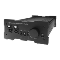
1. The Power Switch. 1 is on, 0 is off... what more can we say?
2. Input Voltage Select. In most cases, the voltage indicator should read
‘115 volts’ for use in the U.S. However, your voltage can be easily adjusted to suit
your needs; call us for details on how to do this yourself.
3. The Ground Lift Switch. For normal use, the Ground Lift Switch should
be on‘float’. For use as a pre-amp, the Ground Lift should be off.
4. Input Two. This is where you would plug in a second source.
5. Input Selector Switch. This switch chooses Input One or Input Two.
6. Input One. Your primary source gets hooked up here.
7. Line Out. If you are using The Max as a pre-amplifier, plug your outputs in
here.
7.
Line
Out
6.
Input 1
5.
Input
Selector
Switch
4.
Input 2
3. Ground
Lift Switch
1.
Power
Switch
2. Input
Voltage Select
Rear Panel- Dual Input Option