5/31/96
36
the battery as possible.
The VIOLET WIRE supplies Battery #2 Voltage for sensing. It should be supplied
directly from Battery #2. Be sure to install the 2Amp fuse shown in the drawing.
Note: If only one battery is to be monitored connect the VIOLET wire to the
BLUE wire.
The GREEN WIRE (B1SHG) is connected to the SMALL SCREW ON THE GROUND
SIDE, OR LOAD SIDE, of the battery #1 shunt (B1SHG). This wire must be located
exactly as described to ensure accuracy of current measurements. The wires that run from
the battery #1 shunt sense terminals to the GREEN AND ORANGE wires should be a
twisted pair.
The ORANGE WIRE (B1SHB) is connected to the SMALL SCREW ON THE
BATTERY SIDE of the battery #1 shunt (B1SHB). This wire should be located exactly
as described to ensure accuracy in current measurements.
NOTE: If only one current input is used, connect the Green and Brown wires
together and the Orange and Yellow wires together. This hookup will display the
same current information for both the battery #1 and #2 selection.
The BROWN WIRE (B2SHG) is connected to the SMALL SCREW ON THE
GROUNDED, OR LOAD SIDE, of the battery #2 shunt (B2SHG). SEE ABOVE
CAUTIONS.
The YELLOW WIRE (B2SHB) is connected to the SMALL SCREW ON THE
BATTERY SIDE of the Battery #2 shunt (B2SHB). The YELLOW and BROWN wires
should be a twisted pair. SEE ABOVE CAUTIONS.
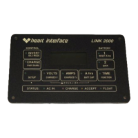
THE INVERTER PHONE CORD
The only connection between the Inverter/Charger and the LINK 2000 is a standard
phone cord. There are three phone plugs on the back (bottom) of the inverter. Use the one
labeled REMOTE. It is best to plug the phone cord into the LINK 2000 after it is powered
up. It is supplied with a 25' cord. You may purchase longer cords from any telephone supply
company. You should limit its length to 50 feet. Do not run the phone cord in the same
wireway as very noisy power conductors. This helps reduce noise interference problems.